Datasheet 搜索 > 开发套件与开发板 > TI(德州仪器) > CC2543-CC2544DK 数据手册 > CC2543-CC2544DK 产品设计参考手册 1/7 页

¥ 2231.948
CC2543-CC2544DK 产品设计参考手册 - TI(德州仪器)
制造商:
TI(德州仪器)
分类:
开发套件与开发板
Pictures:
3D模型
符号图
焊盘图
引脚图
产品图
页面导航:
应用领域在P5P7
导航目录
CC2543-CC2544DK数据手册
Page:
of 7 Go
若手册格式错乱,请下载阅览PDF原文件
SWRU315A
August 2015
Web sites: www.ti.com/lprf
E2E Forum: www.ti.com/lprf-forum
Make sure to subscribe to the Low-Power RF
Newsletter to receive information about updates to
documentation, new product releases, and more.
Sign up on the TI web pages.
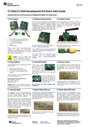
CC2543-CC2544 Development Kit Quick Start Guide
Opening the Box and Running the Packet Error Rate Test Application
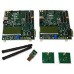
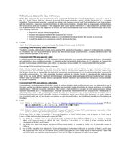
1. Kit Contents
2 x SmartRF05 Evaluation Boards (EB)
2 x CC2543 Evaluation Modules (EM)
2 x Pulse W1010 Antennas
1 x CC2544 USB Dongle
Cables
Documentation
The RF boards in this kit designed, but not
certified, to comply with FCC/IC/ETSI
requirements over temperature from 0 to +35°C.
The antenna, W1010 from Pulse, is a ¼ wave
dipole antenna with 2 dBi gain.
Caution! The kit contains ESD
sensitive components. Handle with
care to prevent permanent damage.
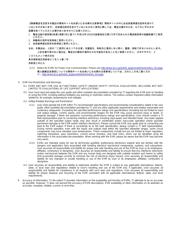
2. Hardware Requirements
To run the PER test described in this Quick Start
Guide, you would need either two CC2543EMs
mounted on SmartRF05 Evaluation Boards
(SmartRF05EB - Rev 1.8.1 or later) or one single
CC2543EM mounted on a SmartRF05EB and a
CC2544 Dongle (powered through USB). Both
the dongle and SmartRF05EB are included in the
CC2543-CC2544DK.
More information about the SmartRF05EB can
be found in www.ti.com/lit/swru210.
The CC2543EM boards can also be plugged into
a battery board (see www.ti.com/tool/soc-bb) for
standalone operation.
The source code for the PER test can be
downloaded from the CC2543-CC2544DK
product page (www.ti.com/tool/cc2543-
cc2544dk).
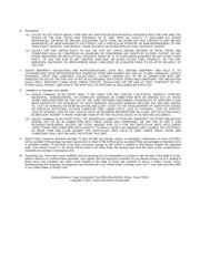
3. Hardware Setup
Connect the antenna to the SMA connector on
the CC2543EM. Tighten the antenna’s screw
firmly on to the SMA connector. If not properly
connected, you might get reduced RF
performance.
Next, mount the CC2543EMs firmly on to
connectors P5 and P6 on the SmartRF05EB.
The CC2544 Dongle can be connected to any
USB port to power the device.
4. Power Options
There are several ways of applying power to the
SmartRF05EB;
USB (5V through USB plug)
External power supply (see below)
2 x 1.5V AA non-rechargeable alkaline
batteries
Voltage regulators on the SmartRF05EB will set
the on-board voltage to 3.3V.
External Power Supply Requirements:
Nom Voltage: 4 to 20 VDC
Max Current: 1500 mA
Efficiency Level V
Warning! Never use rechargeable batteries to
power the board. This can cause personal injury
or damage to the board.
5. Power the Boards
Locate the power
source header P11 just
above the LCD on the
EB. Connect pins 1 and
2 if you are using
battery power. Connect
pins 2 and 3 if you are using USB or an external
power supply.
Once you have set P11,
find switch P8 just next to
the DC jack on the EB. To
power up the boards, flip
the switch from the “OFF”
position to “ON”.
Do not leave the EVM powered when
unattended.
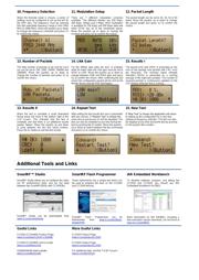
6. Start-up Screen
The CC2543EMs and the CC2544 Dongle will
be pre-loaded with a Packet Error Rate (PER)
test application. The LCD screens on the two
SmartRF05EBs should display the messages
below:
A green led (LED2 on CC2544Dongle, LED1 on
SmartRF05EB) will be lit on power on. For a
master device in beacon mode the led will blink
at a slow pace.
7. Choosing Mode
The application can be used between two
CC2543EM’s or between a single CC2543EM
and the CC2544 Dongle. There are two
operating modes: “Remote” and “Master”.
After button S1 is pushed at the start up screen,
the mode selection screen (showed below) will
appear. The Remote mode is shown by default.
Press the joystick up and down to change
between master and remote mode and press
button S1 to confirm. The CC2544 Dongle is set
to master by default as it is the only option for
this device in this application.
In the Remote mode all the parameters for the
current PER test must be set up before the test
begins (go to step 10).
8. Master Mode (Beacon)
In “Master” mode, the radio will repeatedly (once
every 10 milliseconds) send out a “beacon”
signal (250 kbps, GFSK modulation, 160 kHz
deviation, 2402 MHz) and listen for a response
from the remote device. The Green LED1 will
blink continuously.
No more actions are needed from the user for
the master device to work.
9. Master Mode (PER test)
Once the beacon is acknowledged by the
“Remote”, the actual PER test begins. The PER
test configuration is included in the payload of
the acknowledge packet. The Master device
extracts this information and configures the radio
parameters accordingly. During the PER test,
packets are sent at a fixed repetition rate of 10
msec.
During the test the number of sent packets will
be updated on the LCD display as well as the link
status between the Master and Remote device.
器件 Datasheet 文档搜索
AiEMA 数据库涵盖高达 72,405,303 个元件的数据手册,每天更新 5,000 多个 PDF 文件
