Datasheet 搜索 > 开发套件与开发板 > TI(德州仪器) > CC2595EVM 数据手册 > CC2595EVM 产品设计参考手册 3/10 页

¥ 710.929
CC2595EVM 产品设计参考手册 - TI(德州仪器)
制造商:
TI(德州仪器)
分类:
开发套件与开发板
描述:
射频开发工具 Evaluation Module
Pictures:
3D模型
符号图
焊盘图
引脚图
产品图
CC2595EVM数据手册
Page:
of 10 Go
若手册格式错乱,请下载阅览PDF原文件
www.ti.com
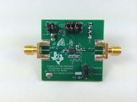
EVM Overview
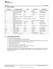
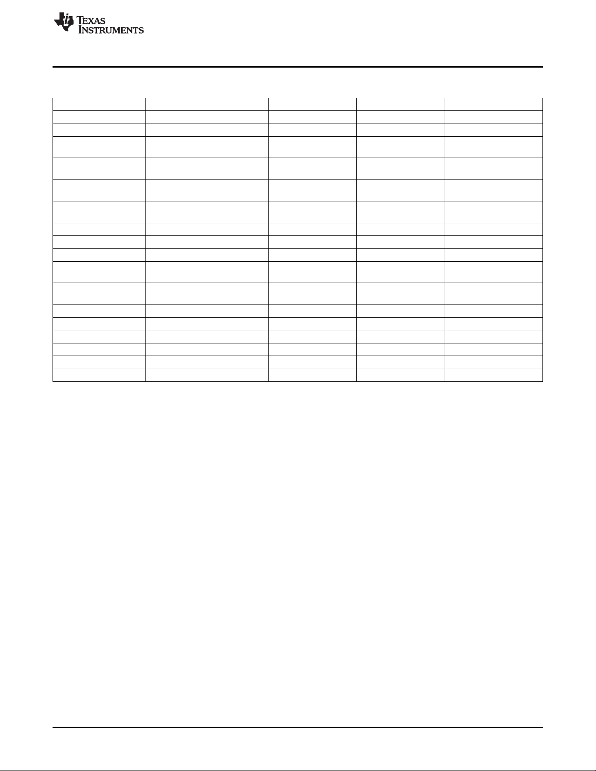
2.2 Bill of Materials
Component Description (footprint) Value Manufacturer Part Number
C2 C3 C7 C11 C14 C85 Power Supply Decoupling (0402) 0.1uF Murata GRM155R71C104KA88D
C9 RFOUT AC Coupling (0402) 22pF Panasonic ECJ-0EC1H220J
C12 Power Supply Decoupling 10uF Vishay Spraque 595D106X0016B2T
(Tantalum)
C13 RFOUT LPF Shunt to GND 1.5pF Panasonic ECJ-0EC1H1R5C
(0402)
J1 Vcc Terminal: Pin 1= 3.3V; 2x2 No Jumpers Installed 3M 929665-09-02-I
Header
J2 Vcc Debug Terminals; 2x8 Jumper (3-4,5-6,7-8) TYCO/AMP 9-146261-0-04
Header
J3 J4 RF Signal SMA connector Johanson Technology 142-0701-801
J5 PAEN Terminal: 1x3 Header Jumper (1-2) Molex 22-28-4033
L1 DC Biasing Inductor (0402) 12nH Toko LL1005-FHL12NJ
L2 RFOUT LPF Series Inductor 1.2nH Toko LL1005-FHL1N2S
(0402)
R1 R2 PAEN pull up/down resistors 10k ohm Vishay/Dale CRCW040210K0FKED
(0402)
R3 RFIN thru (0402) 0 ohm Panasonic ERJ-2GE0R00X
R6, R7 Bias resistors (0402) 20k ohm Panasonic ERJ-2RKF2002X
R8, R11 for biasing options DNI Panasonic ERJ-2RKF2002X
R10 AVDD_PA1 resistor 4.7 ohm Yageo RC0402FR-074R7L
TP1 GND test point Keystone electronics 5015
U1 CC2595 PA, 3x3, 16 pin QFN Texas Instruments CC2595RGT
2.3 General Usage Information
Recommended power-up sequence:
1. Ensure J1 (VCC/GND terminal) has jumpers removed
2. Ensure J2 (VCC debug terminals) has three jumpers installed (pins 3 to 4, pins 5 to 6, and pins 7 to 8)
3. Ensure J5 (PAEN terminal) has one jumper installed (pins 1 to 2)
4. Connect GND to pin 2 of J1
5. Connect VCC to pin 1 of J1; set Vcc to 3.0 V
6. Connect RF input signal to J4 (RFIN), RFIN = 0 dBm at 2.4 GHz
7. Connect measurement instrument to J3 (RFOUT)
In the power-up sequence, VCC should draw approximately 30 mA of current without any RF drive. When
the RFIN signal is applied, the device should output >20 dBm. To power down the device, move the J5
jumper to pins 2 to 3.
3
SWRU362–December 2013 CC2595 EVM User's Guide
Submit Documentation Feedback
Copyright © 2013, Texas Instruments Incorporated
器件 Datasheet 文档搜索
AiEMA 数据库涵盖高达 72,405,303 个元件的数据手册,每天更新 5,000 多个 PDF 文件
