Datasheet 搜索 > 开发套件 > TI(德州仪器) > DRV8871EVM 数据手册 > DRV8871EVM 产品设计参考手册 3/7 页

¥ 352.114
DRV8871EVM 产品设计参考手册 - TI(德州仪器)
制造商:
TI(德州仪器)
分类:
开发套件
描述:
TEXAS INSTRUMENTS DRV8871EVM 评估电路板, 无刷直流电机驱动器
Pictures:
3D模型
符号图
焊盘图
引脚图
产品图
页面导航:
应用领域在P7
导航目录
DRV8871EVM数据手册
Page:
of 7 Go
若手册格式错乱,请下载阅览PDF原文件
www.ti.com
Introduction
1.2 Test Points
Test points are provided and labeled according to the inputs/outputs of the DRV8871 motor driver.
Test point “PWM_R” is generated by a TLC555 located on the EVM. If an externally generated PWM
signal is desired, either:
1. Remove the shunt on IN1 or IN2 and connect the external PWM signal to the IN1 or IN2 test point (this
is recommended), or
2. Remove the 0.0-Ω resistor R5 and connect the external PWM signal to the “PWM_R” test point. The
“PWM” signal generated by the onboard circuitry EVM is approximately 25 kHz and can be adjusted
from 5% to 95% duty cycle by the potentiometer (R6) located on the EVM.
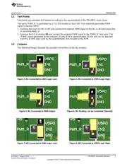
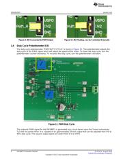
1.3 Jumpers
The following images illustrate the possible connections to the INx jumpers
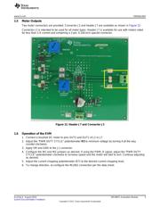
Figure 3. IN1 Connected to GND (Logic Low) Figure 4. IN1 Connected to V5P0 (Logic High)
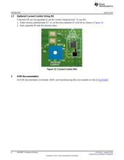
Figure 5. IN1 Connected to PWM Output Figure 6. IN1 Floating, can be Controlled Externally
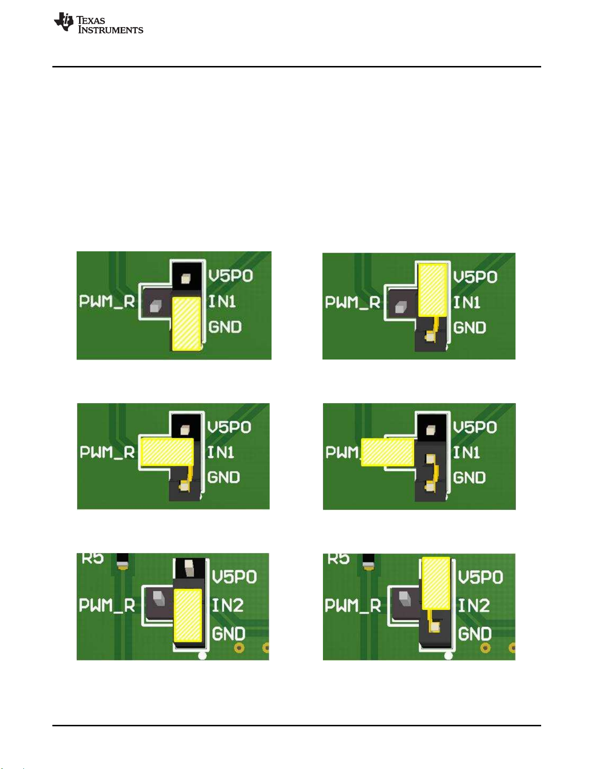
Figure 7. IN2 Connected to GND (Logic Low) Figure 8. IN2 Connected to V5P0 (Logic High)
3
SLVUAJ4–August 2015 DRV8871 Evaluation Module
Submit Documentation Feedback
Copyright © 2015, Texas Instruments Incorporated
器件 Datasheet 文档搜索
AiEMA 数据库涵盖高达 72,405,303 个元件的数据手册,每天更新 5,000 多个 PDF 文件
