Datasheet 搜索 > 微控制器 > Microchip(微芯) > DSPIC30F3013-30I/SP 数据手册 > DSPIC30F3013-30I/SP 产品设计参考手册 6/772 页
 器件3D模型
¥ 36.306
DSPIC30F3013-30I/SP 产品设计参考手册 - Microchip(微芯)
制造商:
Microchip(微芯)
分类:
微控制器
封装:
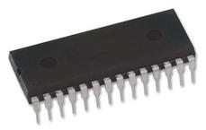
DIP-28
描述:
MICROCHIP DSPIC30F3013-30I/SP 芯片, 16位数字信号控制器
Pictures:
3D模型
符号图
焊盘图
引脚图
产品图
页面导航:
引脚图在P410P469Hot
典型应用电路图在P681
原理图在P23P39P174P212P233P244P253P255P258P266P267P268
技术参数、封装参数在P18P200P202P215P217P218P233P234P241P258P259P273
应用领域在P14P727
电气规格在P18P200P202P215P217P218P233P234P241P258P259P273
型号编号列表在P60P85P98P122P169P209P228P237P249P262P288P303
导航目录
DSPIC30F3013-30I/SP数据手册
Page:
of 772 Go
若手册格式错乱,请下载阅览PDF原文件

70046E-page vi © 2006 Microchip Technology Inc.
PAGE
M
SECTION 12. TIMERS 12-1
Introduction ....................................................................................................................................................12-2
Timer Variants ................................................................................................................................................12-3
Control Registers ...........................................................................................................................................12-6
Modes of Operation ........................................................................................................................................12-9
Timer Prescalers ..........................................................................................................................................12-14
Timer Interrupts ............................................................................................................................................12-14
Reading and Writing 16-bit Timer Module Registers ....................................................................................12-15
Low Power 32 kHz Crystal Oscillator Input ..................................................................................................12-15
32-bit Timer Configuration ............................................................................................................................12-16
32-bit Timer Modes of Operation .................................................................................................................12-18
Reading and Writing into 32-bit Timers ........................................................................................................12-21
Timer Operation in Power Saving States .....................................................................................................12-21
Peripherals Using Timer Modules ................................................................................................................12-22
Design Tips ..................................................................................................................................................12-24
Related Application Notes ............................................................................................................................12-25
Revision History ...........................................................................................................................................12-26
SECTION 13. INPUT CAPTURE 13-1
Introduction ....................................................................................................................................................13-2
Input Capture Registers .................................................................................................................................13-3
Timer Selection ..............................................................................................................................................13-4
Input Capture Event Modes ...........................................................................................................................13-4
Capture Buffer Operation ...............................................................................................................................13-8
Input Capture Interrupts .................................................................................................................................13-9
UART Autobaud Support ...............................................................................................................................13-9
Input Capture Operation in Power Saving States ........................................................................................13-10
I/O Pin Control ..............................................................................................................................................13-10
Special Function Registers Associated with the Input Capture Module .......................................................13-11
Design Tips ..................................................................................................................................................13-12
Related Application Notes ............................................................................................................................13-13
Revision History ...........................................................................................................................................13-14
SECTION 14. OUTPUT COMPARE 14-1
Introduction ....................................................................................................................................................14-2
Output Compare Registers ............................................................................................................................14-3
Modes of Operation ........................................................................................................................................14-4
Output Compare Operation in Power Saving States ....................................................................................14-23
I/O Pin Control ..............................................................................................................................................14-23
Design Tips ..................................................................................................................................................14-26
Related Application Notes ............................................................................................................................14-27
Revision History ...........................................................................................................................................14-28
Table of Contents
器件 Datasheet 文档搜索
AiEMA 数据库涵盖高达 72,405,303 个元件的数据手册,每天更新 5,000 多个 PDF 文件
