Datasheet 搜索 > 电容 > Panasonic(松下) > EEUFC1V560 数据手册 > EEUFC1V560 产品设计参考手册 1/6 页

¥ 0.849
EEUFC1V560 产品设计参考手册 - Panasonic(松下)
制造商:
Panasonic(松下)
分类:
电容
描述:
PANASONIC ELECTRONIC COMPONENTS EEUFC1V560 铝电解电容, AEC-Q200 FC系列, 56 µF, ± 20%, 35 V, 6.3 mm, 径向引线
Pictures:
3D模型
符号图
焊盘图
引脚图
产品图
页面导航:
焊接温度在P5
应用领域在P3
导航目录
EEUFC1V560数据手册
Page:
of 6 Go
若手册格式错乱,请下载阅览PDF原文件
Design and specifi cations are subject to change without notice. Ask factory for technical specifi cations before purchase and/or use.
Whenever a doubt about safety arises from this product, please contact us immediately for technical consultation.
Aluminum Electrolytic Capacitors
Application Guidelines
1. Circuit Design
Ensure that operational and mounting conditions
follow the specified conditions detailed in the catalog
and specification sheets.
1.1 Operating Temperature and Frequency
Electrolytic capacitor electrical parameters are
normally specified at 20°C temperature and 120Hz
frequency. These parameters vary with changes in
temperature and frequency. Circuit designers
should take these changes into consideration.
(1) Effects of operating temperature on electrical
parameters
a)At higher temperatures, leakage current and
capacitance increase while equivalent series
resistance(ESR) decreases.
b)At lower temperatures, leakage current and
capacitance decrease while equivalent series
resistance(ESR) increases.
(2) Effects of frequency on electrical parameters
a)At higher frequencies, capacitance and
impedance decrease while tan δ increases.
b)At lower frequencies, ripple current generated
heat will rise due to an increase in equivalent
series resistance (ESR).
1.2 Operating Temperature and Life Expectancy
(1) Expected life is affected by operating temperature.
Generally, each 10°C reduction in temperature
will double the expected life. Use capacitors at
the lowest possible temperature below the
maximum guaranteed temperature.
(2) If operating conditions exceed the maximum
guaranteed limit, rapid eIectrical parameter
deterioration will occur, and irreversible damage
will result.
Check for maximum capacitor operating tempera-
tures including ambient temperature, internal
capacitor temperature rise caused by ripple current,
and the effects of radiated heat from power
transistors, IC'sor resistors.
Avoid placing components which could conduct
heat to the capacitor from the back side of the circuit
board.
(3)The formula for calculating expected Iife at lower
operating temperatures is as follows;
L
2 = L1 x 2 where,
L
1: Guaranteed life (h) at temperature, T1° C
L
2: Expected life (h) at temperature,T2°C
T
1: Maximum operating temperature (°C)
T
2: Actual operating temperature, ambient
temperature + temperature rise due to
ripple current heating(°C)
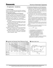
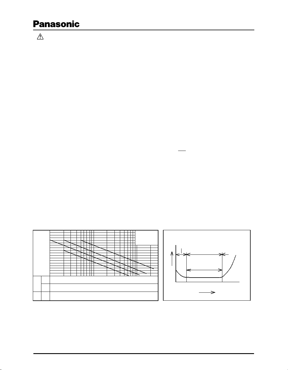
A quick reference capacitor guide for estimating
expected life is included for your reference.
2000 5000 10,000 20,000 50,000 100,000 200,000
120
110
100
90
80
70
60
50
40
8h/d
1 2 3 4 5 7 20
3
6 10 15 20 30
■ Expected Life Estimate Quick Reference Guide
■ Failure rate curve
1. 85°C2000h
2.105°C1000h
3.105°C2000h
4.105°C5000h
1
2
3
4
Capacitor Ambient Temperature
(h)
Years
Years
24h
operat-
ion
Failure rate
Time
Initial failure period
Life Time
Random failure period
Wear failure period
T1-T2
10
器件 Datasheet 文档搜索
AiEMA 数据库涵盖高达 72,405,303 个元件的数据手册,每天更新 5,000 多个 PDF 文件
