Datasheet 搜索 > LED驱动器 > TI(德州仪器) > LM3423MHBKBSTEV/NOPB 数据手册 > LM3423MHBKBSTEV/NOPB 产品设计参考手册 1/17 页

¥ 582.494
LM3423MHBKBSTEV/NOPB 产品设计参考手册 - TI(德州仪器)
制造商:
TI(德州仪器)
分类:
LED驱动器
Pictures:
3D模型
符号图
焊盘图
引脚图
产品图
页面导航:
引脚图在P3Hot
原理图在P13
应用领域在P17
导航目录
LM3423MHBKBSTEV/NOPB数据手册
Page:
of 17 Go
若手册格式错乱,请下载阅览PDF原文件
User's Guide
SNVA376A–December 2008–Revised May 2013
AN-1907 LM3423 Buck-Boost Configuration Evaluation
Board
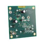
1 Introduction
This evaluation board has been designed to demonstrate the LM3423 low-side controller as a step-
up/step-down (buck-boost) regulator to deliver constant current to high power LEDs. A complete circuit
schematic and bill of materials for the evaluation board are included at the end of this document. The
printed circuit board consists of two layers of two ounce copper on FR4 material. The LM3423 evaluation
board is designed so that all options available can be evaluated and tested. Most applications will only
require a few options therefore jumpers can be placed, or removed as needed. A schematic of the full
featured LM3423 evaluation board and its bill of materials is provided in this document. Simplified design
examples with schematics and a bill of materials follow.
2 Device Description
The LM3423 is a high voltage, low-side NFET controller with an adjustable output current sense voltage.
Output voltage regulation is based on peak current-mode control, which eases the design of loop
compensation while providing inherent input voltage feed-forward compensation. The LM3423 includes a
high-voltage start-up regulator that operates over a wide input range of 4.5V to 75V. The PWM controller
is designed for high speed capability including a switching frequency range to 2.0 MHz. Additional features
include “zero” current shutdown, error amplifier, precision reference, logic-compatible DIM input suitable
for fast PWM dimming of the output, cycle-by-cycle current limit, LED ready flag, fault flag, programmable
fault timer, and thermal shutdown.
Standard Evaluation Board Operating Configuration
• f
SW
= 600 kHz
• Over-voltage protection set at 56V
• V
IN
range 4.5V to 35V
• Low side PWM fast dimming
• 2 to 8 series connected LEDs (V
O
< 35V)
• UVLO set at 8.4V
• I
LED
= 1A
Available features that can be configured on the standard evaluation board by the user for are listed
below:
• Fixed or programmable LED current
• High-speed PWM high-side or low-side dimming
• User programmable over-voltage protection (OVP)
• Under-voltage lock-out (UVLO) protection
• Fault protection
• Soft-start
• Hysteretic current-mode control
All trademarks are the property of their respective owners.
1
SNVA376A–December 2008–Revised May 2013 AN-1907 LM3423 Buck-Boost Configuration Evaluation Board
Submit Documentation Feedback
Copyright © 2008–2013, Texas Instruments Incorporated
器件 Datasheet 文档搜索
AiEMA 数据库涵盖高达 72,405,303 个元件的数据手册,每天更新 5,000 多个 PDF 文件
