Datasheet 搜索 > TI(德州仪器) > LMH1981MTEVAL 数据手册 > LMH1981MTEVAL 产品设计参考手册 1/5 页


¥ 0
LMH1981MTEVAL 产品设计参考手册 - TI(德州仪器)
制造商:
TI(德州仪器)
Pictures:
3D模型
符号图
焊盘图
引脚图
产品图
页面导航:
原理图在P2
功能描述在P1
应用领域在P5

导航目录
LMH1981MTEVAL数据手册
Page:
of 5 Go
若手册格式错乱,请下载阅览PDF原文件

User's Guide
SNLA094C–February 2007–Revised April 2013
AN-1599 LMH1981 Evaluation Board Instruction Manual
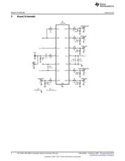
1 General Description
The LMH1981 evaluation board can be used to evaluate the LMH1981 multi-format sync separator and as
a reference for designing the PCB layout. For more information on PCB layout considerations, see the
LMH1981 Multi-Format Video Sync Separator Data Sheet (SNLS214).
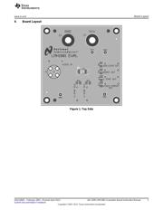
2 Power Supply
The board should be powered with a clean supply voltage of 3.3 V to 5.0 V using the banana jacks V
CC
(J2) and GND (J3). The supply should be well-regulated within ±5% variation of the voltage range and
should not be shared directly with other digital circuitry.
3 Video Input
A high-quality DC-coupled video source should be connected to the video input BNC (J1), which is
terminated on-board via a 75 Ω load resistor. For AC-coupled video sources, it may be necessary to
reduce the value of the input coupling capacitor (C4) as described in the data sheet; otherwise, sync loss
may occur during significant changes in video average picture level (random white-to-black field
transitions). It is recommended to drive the LMH1981 input by a professional-grade DC-coupled video
reference.
Because the input can accept either SD or HD video inputs, the PCB footprints for the chroma filter
components were not populated. For SD composite video inputs, it may be necessary to use a RC low-
pass filter to attenuate the chroma component so it does not extend below the 50% sync level and also to
improve overall signal-to-noise ratio. The RC filter cutoff frequency is typically set between 0.5 MHz and 2
MHz, which corresponds to chroma attenuation between 17 dB and 6 dB for a 3.58 MHz subcarrier
(NTSC). For HD video inputs, it is suggested to bypass any composite video filtering, as it may reduce the
bandwidth of the HD tri-level sync signal and, thus, increase timing jitter on the HSync output.
4 Test Points
Test points are provided to probe the input and output signals using oscilloscope probes with high input
impedance and low capacitance.
All trademarks are the property of their respective owners.
1
SNLA094C–February 2007–Revised April 2013 AN-1599 LMH1981 Evaluation Board Instruction Manual
Submit Documentation Feedback
Copyright © 2007–2013, Texas Instruments Incorporated
器件 Datasheet 文档搜索
AiEMA 数据库涵盖高达 72,405,303 个元件的数据手册,每天更新 5,000 多个 PDF 文件
