Datasheet 搜索 > 开发套件 > TI(德州仪器) > LMZ31710X2EVM 数据手册 > LMZ31710X2EVM 产品设计参考手册 1/22 页

¥ 423.101
LMZ31710X2EVM 产品设计参考手册 - TI(德州仪器)
制造商:
TI(德州仪器)
分类:
开发套件
Pictures:
3D模型
符号图
焊盘图
引脚图
产品图
页面导航:
原理图在P12P13P15P16
功能描述在P2P4
应用领域在P20P22
导航目录
LMZ31710X2EVM数据手册
Page:
of 22 Go
若手册格式错乱,请下载阅览PDF原文件

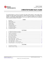
User's Guide
SLVUA04–February 2014
LMZ31710 Parallel User's Guide
The LMZ31710 device is a 2.95-V to 17-V input, 10-A output, Simple Switcher™ power module, which
integrates the PWM controller, power MOSFETs, shielded inductor, and passives in a low-profile, QFN
package. For applications requiring greater than 10 A, it is possible to parallel up to six LMZ31710
devices. This user's guide provides information on the correct usage of the test board and an explanation
of the test points and jumpers on the board.
Contents
1 Description ................................................................................................................... 2
2 Getting Started .............................................................................................................. 2
3 Test Point Descriptions ..................................................................................................... 4
4 Operation Notes ............................................................................................................. 4
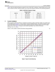
5 Current Limitations .......................................................................................................... 5
6 Performance Data ........................................................................................................... 6
7 2× Parallel Bill of Material ................................................................................................ 11
8 2× Parallel Schematic ..................................................................................................... 12
9 4× Parallel Bill of Material ................................................................................................ 14
10 4× Parallel Schematic ..................................................................................................... 15
List of Figures
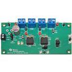
1 2× LMZ31710 Test Board User Interface................................................................................ 2
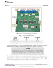
2 4× LMZ31710 Test Board User Interface................................................................................ 3
3 Typical Current Balancing ................................................................................................. 5
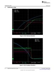
4 UVLO Start-Up Waveform ................................................................................................. 6
5 UVLO Shutdown Waveform ............................................................................................... 6
6 INH Start-Up Waveform.................................................................................................... 7
7 INH Shutdown Waveform.................................................................................................. 7
8 Output Voltage Ripple – In-Phase........................................................................................ 8
9 Output Voltage Ripple – 180° Out-of-Phase ............................................................................ 8
10 Input Voltage Ripple – In-Phase .......................................................................................... 9
11 Input Voltage Ripple – 180° Out-of-Phase .............................................................................. 9
12 Transient Response – 10-A Load Step (1 A/µs) ...................................................................... 10
List of Tables
1 Terminal Block Numbering................................................................................................. 3
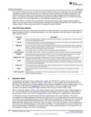
2 Switching Frequency Range............................................................................................... 5
1
SLVUA04–February 2014 LMZ31710 Parallel User's Guide
Submit Documentation Feedback
Copyright © 2014, Texas Instruments Incorporated
器件 Datasheet 文档搜索
AiEMA 数据库涵盖高达 72,405,303 个元件的数据手册,每天更新 5,000 多个 PDF 文件
