Datasheet 搜索 > 微控制器 > NXP(恩智浦) > LPC2131FBD64,151 数据手册 > LPC2131FBD64,151 产品设计参考手册 2/297 页
 器件3D模型
¥ 4.697
LPC2131FBD64,151 产品设计参考手册 - NXP(恩智浦)
制造商:
NXP(恩智浦)
分类:
微控制器
封装:
LQFP-64
描述:
ARM微控制器 - MCU 32K FL/8K RM/10B ADC/LV RTC
Pictures:
3D模型
符号图
焊盘图
引脚图
产品图
页面导航:
引脚图在P22P23P27P43P47P49P50P51P52P53P54P55Hot
原理图在P8P74P217P267P270
功能描述在P96P112
应用领域在P4P48P58P79P152P174P175P176P177P178P180P191
导航目录
LPC2131FBD64,151数据手册
Page:
of 297 Go
若手册格式错乱,请下载阅览PDF原文件

UM10120 All information provided in this document is subject to legal disclaimers. © NXP B.V. 2012. All rights reserved.
User manual Rev. 4 — 23 April 2012 2 of 297
Contact information
For more information, please visit: http://www.nxp.com
For sales office addresses, please send an email to: salesaddresses@nxp.com
NXP Semiconductors
UM10120
LPC213x and LPC213x/01 UM
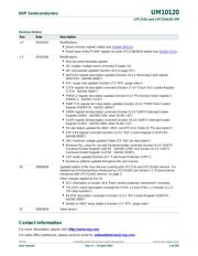
Revision history
Rev Date Description
v 4 20120423 Modifications:
• Device revision register added (see Section 20.8.11).
• Reset value of the PCONP register for parts LPC2138/36/34 added (see Section 4.9.3).
v 3 20101004 Modifications:
• New document template applied.
• I2C chapter: multiple errors corrected (Chapter 13).
• IAP call example updated (Section 20.9 on page 257).
• WDFEED register description updated (Section 16.4.3 “Watchdog Feed register
(WDFEED - 0xE000 0008)”).
• RTC usage note updated (Section 17.5 “RTC usage notes”).
• CTCR register bit description corrected (Section 17.4.4 “Clock Tick Counter Register
(CTCR - 0xE002 4004)”).
• PINSEL2 register description updated (Section 6.4.3 “Pin function Select register 2
(PINSEL2 - 0xE002 C014)”).
• PWM TCR register bit 3 description updated (Section 15.4.2 “PWM Timer Control
Register (PWMTCR - 0xE001 4004)”).
• U0IER register bit description corrected (Section 9.3.6 “UART0 Interrupt Enable
Register (U0IER - 0xE000 C004, when DLAB = 0)”).
• U1IER register bit description corrected (Section 10.3.6 “UART1 Interrupt Enable
Register (U1IER - 0xE001 0004, when DLAB = 0)”).
• Pin description updated for VBAT, VREF, and RTCX1/2 (Table 35 “Pin description”).
• SSP CR0 register corrected (Section 12.4.1 “SSP Control Register 0 (SSPCR0 -
0xE006 8000)”).
• ADC maximum voltage updated (Table 213 “ADC pin description”).
• Minimum DLL value for use with fractional divider corrected (Section 9.3.4 “UART0
Fractional Divider Register (U0FDR - 0xE000 C028)” and Section 10.3.4 “UART1
Fractional Divider Register (U1FDR - 0xE001 0028)”).
• CRP levels updated (Section 20.7 “Code Read Protection (CRP)”).
• Numerous editorial updated throughout the user manual.
02 20060918 Updated edition of the User Manual covering both LPC213x and LPC213x/01 devices. For
detailed list of enhancements introduced by LPC213x/01 see Section 1.2 “Enhancements
introduced with LPC213x/01 devices” on page 3.
Other changes applied to Rev 01:
• ECC information in Section 20.6 “Flash content protection mechanism” corrected
• The SSEL signal description corrected for CPHA = 0 and CPHA = 1 (Section 11.2.2
“SPI data transfers”)
• Bit SPIE description corrected in Section 11.4.1 “SPI Control Register (S0SPCR -
0xE002 0000)”
• Details on VBAT setup added in Section 17.5 “RTC usage notes”
01 20050624 Initial version
器件 Datasheet 文档搜索
AiEMA 数据库涵盖高达 72,405,303 个元件的数据手册,每天更新 5,000 多个 PDF 文件
