Datasheet 搜索 > 8位微控制器 > Microchip(微芯) > PIC16F723-I/SP 数据手册 > PIC16F723-I/SP 产品设计参考手册 4/137 页
 器件3D模型
¥ 15.381
PIC16F723-I/SP 产品设计参考手册 - Microchip(微芯)
制造商:
Microchip(微芯)
分类:
8位微控制器
封装:
DIP-28
描述:
PIC16F722/723/724/726/727 8 位闪存微控制器Microchip 的 PIC16F 系列微控制器 8 位 MCU,将 Microchip 的 PIC® 体系架构融入到引脚和封装选件中,从节省空间的 14 引脚设备到功能丰富的 64 引脚设备。 带有基线、中级或增强型中级体系架构的设备提供多种不同的外围设备组合,可谓设计人员提供灵活性,并为应用提供选择。 PIC16F722/723/724/726/727 系列微控制器基于 Microchip 的中级内核,带 8 层深硬件堆栈和 35 个指令。 这些 MCU 提供高达 5 个 MIP、14 千字节程序存储器和 368 字节 RAM。 板载是一个振荡器,工厂校准到 ±1% 精确度。### 微控制器功能最大 20 MHz CPU 速度 35 指令 8 级硬件堆栈 25 个输入/输出引脚 – PIC16F722/723/726 型号 36 个输入/输出引脚 – PIC16F724/727 型号 nanoWatt XLP 技术 通电重置 (POR) 通电计时器 (PWRT) 振荡器启动计时器 (OST) 掉电重置 (BOR) 监控器计时器 (WDT) 在线串行编程 (ICSP) 在线调试 (ICD) ### 外设8 位模拟到数字转换器 (ADC) - PIC16F722/723/726 11 通道、PIC16F724/727 14 通道 mTouchTM 电容式触摸传感振荡器模块 - PIC16F722/723/726 8 通道、PIC16F724/727 16 通道 两个捕获、比较、PWM (CCP) 模块 两个 8 位计时器 一个 16 位计时器 可寻址通用同步异步接收器发送器 (AUSART) 同步串行端口 (SSP),带有 SPI 和 I2C展开
Pictures:
3D模型
符号图
焊盘图
引脚图
产品图
页面导航:
原理图在P94P98P100P106P107P110P112P113P114
应用领域在P29P83
导航目录
PIC16F723-I/SP数据手册
Page:
of 137 Go
若手册格式错乱,请下载阅览PDF原文件

© 2009 Microchip Technology Inc.Page ii-DS01146B
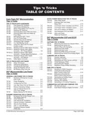
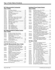
Tips ‘n Tricks Table of Contents
PIC
®
Microcontroller Comparator
Tips ‘n Tricks
TIP #1: Low Battery Detection ................................ 4-2
TIP #2: Faster Code for Detecting Change............. 4-3
TIP #3: Hysteresis................................................... 4-4
TIP #4: Pulse Width Measurement ......................... 4-5
TIP #5: Window Comparison .................................. 4-6
TIP #6: Data Slicer .................................................. 4-7
TIP #7: One-Shot .................................................... 4-8
TIP #8: Multi-Vibrator (Square Wave Output) ......... 4-9
TIP #9: Multi-Vibrator (Ramp Wave Output) ...........4-10
TIP #10: Capacitive Voltage Doubler ........................4-11
TIP #11: PWM Generator .........................................4-12
TIP #12: Making an Op Amp Out of a Comparator ...4-13
TIP #13: PWM High-Current Driver ..........................4-14
TIP #14: Delta-Sigma ADC .......................................4-15
TIP #15: Level Shifter ...............................................4-16
TIP #16: Logic: Inverter.............................................4-16
TIP #17: Logic: AND/NAND Gate .............................4-17
TIP #18: Logic: OR/NOR Gate..................................4-18
TIP #19: Logic: XOR/XNOR Gate .............................4-19
TIP #20: Logic: Set/Reset Flip Flop ..........................4-20
PIC
®
Microcontroller DC Motor Control
Tips ‘n Tricks
TIP #1: Brushed DC Motor Drive Circuits ............... 5-2
TIP #2: Brushless DC Motor Drive Circuits ............. 5-3
TIP #3: Stepper Motor Drive Circuits ...................... 5-4
TIP #4: Drive Software ............................................ 5-6
TIP #5: Writing a PWM Value to the CCP
Registers with a Mid-Range PIC
®
MCU ..... 5-7
TIP #6: Current Sensing ......................................... 5-8
TIP #7: Position/Speed Sensing ............................. 5-9
Application Note References .........................................5-11
Motor Control Development Tools .................................5-11
LCD PIC
®
Microcontroller Tips ‘n Tricks
TIP #1: Typical Ordering Considerations and
Procedures for Custom Liquid Displays ..... 6-2
TIP #2: LCD PIC
®
MCU Segment/Pixel Table ......... 6-2
TIP #3: Resistor Ladder for Low Current ................ 6-3
TIP #4: Contrast Control with a Buck Regulator ..... 6-5
TIP #5: Contrast Control Using a Boost
Regulator .................................................... 6-5
TIP #6: Software Controlled Contrast with
PWM for LCD Contrast Control .................. 6-6
TIP #7: Driving Common Backlights ....................... 6-7
TIP #8: In-Circuit Debug (ICD) ................................ 6-8
TIP #9: LCD in Sleep Mode .................................... 6-8
TIP #10: How to Update LCD Data
Through Firmware ...................................... 6-9
TIP #11: Blinking LCD............................................... 6-9
TIP #12: 4 x 4 Keypad Interface that Conserves
Pins for LCD Segment Drivers ...................6-10
Application Note References .........................................6-11
Intelligent Power Supply Design
Tips ‘n Tricks
TIP #1: Soft-Start Using a PIC10F200 .................... 7-2
TIP #2: A Start-Up Sequencer ................................ 7-3
TIP #3: A Tracking and Proportional
Soft-Start of Two Power Supplies ............... 7-4
TIP #4: Creating a Dithered PWM Clock ................ 7-5
TIP #5: Using a PIC
®
Microcontroller as a Clock
Source for a SMPS PWM Generator.......... 7-6
TIP #6: Current Limiting Using the MCP1630 ......... 7-7
TIP #7: Using a PIC
®
Microcontroller for
Power Factor Correction ............................ 7-8
TIP #8: Transformerless Power Supplies ............... 7-9
TIP #9: An IR Remote Control Actuated AC
Switch for Linear Power Supply Designs ...7-10
TIP #10: Driving High Side FETs ..............................7-11
TIP #11: Generating a Reference Voltage with a
PWM Output ...............................................7-12
TIP #12: Using Auto-Shutdown CCP ........................7-13
TIP #13: Generating a Two-Phase Control Signal ....7-14
TIP #14: Brushless DC Fan Speed Control ..............7-15
TIP #15: High Current Delta-Sigma Based Current
Measurement Using a Slotted Ferrite
and Hall Effect Device ................................7-16
TIP #16: Implementing a PID Feedback Control
in a PIC12F683-Based SMPS Design........7-17
TIP #17: An Error Detection and Restart Controller..7-18
TIP #18: Data-Indexed Software State Machine.......7-19
TIP #19: Execution Indexed Software
State Machine ............................................7-20
TIP #20: Compensating Sensors Digitally ................7-21
TIP #21: Using Output Voltage Monitoring to
Create a Self-Calibration Function .............7-22
3V Tips ‘n Tricks
TIP #1: Powering 3.3V Systems From 5V
Using an LDO Regulator ............................ 8-3
TIP #2: Low-Cost Alternative Power System
Using a Zener Diode .................................. 8-4
TIP #3: Lower Cost Alternative Power System
Using 3 Rectier Diodes ............................. 8-4
TIP #4: Powering 3.3V Systems From 5V
Using Switching Regulators ....................... 8-5
TIP #5: 3.3V → 5V Direct Connect ......................... 8-6
TIP #6: 3.3V → 5V Using a MOSFET Translator .... 8-6
TIP #7: 3.3V → 5V Using A Diode Offset ................ 8-7
TIP #8: 3.3V → 5V Using A Voltage Comparator .... 8-8
TIP #9: 5V → 3.3V Direct Connect ......................... 8-9
TIP #10: 5V → 3.3V With Diode Clamp .................... 8-9
TIP #11: 5V → 3.3V Active Clamp ............................8-10
TIP #12: 5V → 3.3V Resistor Divider........................8-10
TIP #13: 3.3V → 5V Level Translators......................8-12
TIP #14: 3.3V → 5V Analog Gain Block....................8-13
TIP #15: 3.3V → 5V Analog Offset Block ..................8-13
TIP #16: 5V → 3.3V Active Analog Attenuator ..........8-14
TIP #17: 5V → 3V Analog Limiter .............................8-15
TIP #18: Driving Bipolar Transistors .........................8-16
TIP #19: Driving N-Channel MOSFET Transistors ...8-18
器件 Datasheet 文档搜索
AiEMA 数据库涵盖高达 72,405,303 个元件的数据手册,每天更新 5,000 多个 PDF 文件
