Datasheet 搜索 > 微控制器 > Microchip(微芯) > PIC24FJ128GA202-I/SP 数据手册 > PIC24FJ128GA202-I/SP 产品设计参考手册 1/22 页
 器件3D模型
¥ 25.494
PIC24FJ128GA202-I/SP 产品设计参考手册 - Microchip(微芯)
制造商:
Microchip(微芯)
分类:
微控制器
封装:
SDIP-28
描述:
MICROCHIP PIC24FJ128GA202-I/SP 微控制器, 16位, 通用, PIC24FJ, 32 MHz, 128 KB, 8 KB, 28 引脚, SDIP
Pictures:
3D模型
符号图
焊盘图
引脚图
产品图
页面导航:
应用领域在P18P20
电气规格在P19
导航目录
PIC24FJ128GA202-I/SP数据手册
Page:
of 22 Go
若手册格式错乱,请下载阅览PDF原文件
2011 Microchip Technology Inc. DS01416A-page 1
AN1416
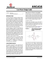
INTRODUCTION
Low-power applications represent a significant portion
of the future market for embedded systems. Every
year, more designers are required to make designs
portable, wireless and energy efficient. This document
seeks to simplify the transition to low-power applica-
tions by providing a single location for the foundations
of low-power design for embedded systems. The
examples discussed in this document will focus on
power consumption from the viewpoint of the microcon-
troller (MCU). As the brain of the application, the MCU
typically consumes the most power and has the most
control over the system power consumption.
As with all designs, it is important for the designer of a
low-power embedded system to consider trade-offs
between power consumption, and other factors, such as
cost, size and complexity. While some low-power tech-
niques can be used with no cost to the system, others
may require trade-offs. This guide will give examples of
these trade-offs where applicable. However, it is not
feasible to discuss all possible trade-offs, so an embed-
ded designer should keep in mind the possible system
level impacts of power-saving techniques.
This design guide will refer to Low-Power modes
available on PIC
®
MCUs, but will not go into detail
about these features. For information about the
Low-Power modes available on PIC MCU devices,
refer to AN1267, “nanoWatt and nanoWatt XLP™
Technologies: An Introduction to Microchip’s
Low-Power Devices” (DS01267).
LOW-POWER BASICS
The definition of low power varies significantly from
application to application. In some systems, there is
plenty of energy available to run from, but the
low-power designer is attempting to minimize operating
costs or maximize efficiency. While in other applica-
tions, there may be a limited power supply, such as a
coin cell battery, which determines the power con-
sumption requirements of the system. These systems
require different focuses to minimize power. It is impor-
tant to consider and understand what causes power
consumption and where to focus power minimization
efforts to create an effective low-power system.
Main Sources of Power Consumption
In CMOS devices, such as microcontrollers, the total
power consumption can be broken down into two broad
categories: dynamic power and static power. Dynamic
power is the power consumed when the microcontroller
is running and performing its programmed tasks. Static
power is the power consumed, when not running code,
that occurs simply by applying voltage to a device.
DYNAMIC POWER
Dynamic power consumption is the current which is
consumed during the normal operation of an MCU. It
includes the power lost in switching CMOS circuits and
the bias currents for the active analog circuits of the
device, such as A/Ds or oscillators.
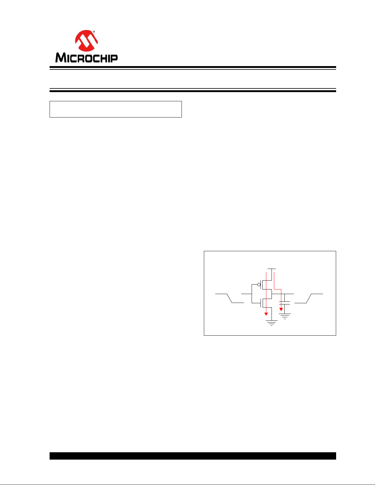
To understand where switching losses originate from,
consider a CMOS inverter, as shown in Figure 1.
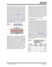
FIGURE 1: CMOS INVERTER DYNAMIC
POWER CONSUMPTION
PATHS
This inverter will consume little to no power when the
input is at V
DD or VSS. However, when the signal
switches from V
DD to VSS, there is a transition period
where the PMOS and NMOS will both be biased in the
linear region, allowing current to flow from V
DD to
ground. Also note, in a real system there is some
amount of load capacitance on the output bus. There is
additional current consumption associated with the
charging and discharging of this bus capacitance when
the logic level changes.
Authors: Brant Ivey
Microchip Technology Inc.
VDD
OutputInput
Low-Power Design Guide
器件 Datasheet 文档搜索
AiEMA 数据库涵盖高达 72,405,303 个元件的数据手册,每天更新 5,000 多个 PDF 文件
