Datasheet 搜索 > 开发套件 > TI(德州仪器) > TCA8418E-EVM 数据手册 > TCA8418E-EVM 产品设计参考手册 4/23 页


¥ 539.243
TCA8418E-EVM 产品设计参考手册 - TI(德州仪器)
制造商:
TI(德州仪器)
分类:
开发套件
Pictures:
3D模型
符号图
焊盘图
引脚图
产品图
页面导航:
原理图在P14
应用领域在P20P23
导航目录
TCA8418E-EVM数据手册
Page:
of 23 Go
若手册格式错乱,请下载阅览PDF原文件
COL9 COL8 COL7 COL6 COL5 COL4
GND V
CC
ROW7 ROW6 ROW5 ROW4
COL3 COL2 COL1
ROW3 ROW2 ROW1
COL0
ROW0
J5
Setup
www.ti.com
5 Setup
This section describes the header/jumper connections on the TCA8418E-EVM, installation of the firmware
on the MSP430 LaunchPad, installation of the software (GUI) on the computer, and getting started using
the TCA8418E-EVM with any of the supported devices.
5.1 Header/Jumper Connections Description
5.1.1 TP1: Power Input
Test point TP1 allows power input without the LaunchPad. The range is 1.65 V to 3.6 V.
5.1.2 TP2 and TP3: Ground
Test points TP2 and TP3 are connected to ground.
5.1.3 J1 and J2: MSP430 LaunchPad Interface Headers
Headers J1 and J2 are the connectors for the MSP430 LaunchPad to the TCA8418E-EVM.
5.1.4 J3: I
2
C Test Points
Header J3 is a test point for SDA and SCL, and allows I
2
C input when the LaunchPad is not present.
5.1.5 J4: RESET and Interrupt Test Points
Test point J4 is a test point for the RESET input, INT output, and CAD_INT output.
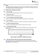
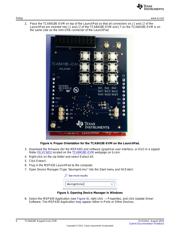
5.1.6 J5: Keypad Extension Header
Header J5 allows extension of the functionality of the TCA8418E-EVM onto a larger keypad or GPIO
expander board.
Figure 2. Header J5 Connections to TCA8418E Pins (Top View)
5.1.7 SW1, SW2, SW3, SW11, SW12, SW13, SW21, SW22, SW23: Keypad Switches
These switches are named in accordance with the Key Value Assignment table in the TCA8418E
(SCPS222) datasheet. They are for ROW0-ROW2 and COL0-COL2, which are programmed as keypad
I/Os, by default, on the TCA8418E-EVM.
4
TCA8418E Keypad Scan EVM SLVUAA2–August 2014
Submit Documentation Feedback
Copyright © 2014, Texas Instruments Incorporated
器件 Datasheet 文档搜索
AiEMA 数据库涵盖高达 72,405,303 个元件的数据手册,每天更新 5,000 多个 PDF 文件
