Datasheet 搜索 > DSP数字信号处理器 > TI(德州仪器) > TMS320C5514AZCH10 数据手册 > TMS320C5514AZCH10 产品设计参考手册 1/146 页
 器件3D模型
¥ 59.464
TMS320C5514AZCH10 产品设计参考手册 - TI(德州仪器)
制造商:
TI(德州仪器)
分类:
DSP数字信号处理器
封装:
LFBGA-196
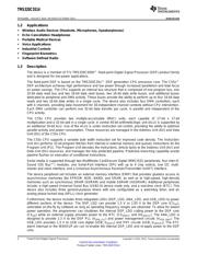
描述:
TMS320C5514定点Dight信号处理器 TMS320C5514 Fixed-Point Dight Signal Processor
Pictures:
3D模型
符号图
焊盘图
引脚图
产品图
页面导航:
引脚图在P14P54P57Hot
典型应用电路图在P121
原理图在P4
封装尺寸在P142
标记信息在P142
封装信息在P141P142P143
功能描述在P53
技术参数、封装参数在P11P63P67P68P69P70P71P72P73P74P75P76
应用领域在P2P145
电气规格在P11P38P61P65P66P67P68P69P70P71P72P73
导航目录
TMS320C5514AZCH10数据手册
Page:
of 146 Go
若手册格式错乱,请下载阅览PDF原文件
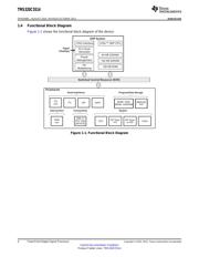
TMS320C5514
www.ti.com
SPRS646G –AUGUST 2010–REVISED OCTOBER 2013
TMS320C5514 Fixed-Point Digital Signal Processor
Check for Samples: TMS320C5514
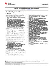
1 Fixed-Point Digital Signal Processor
1.1 Features
12
• High-Performance, Low-Power, TMS320C55x™ • Master/Slave Inter-Integrated Circuit (I
2
C Bus™)
Fixed-Point Digital Signal Processor
• Four Inter-IC Sound (I
2
S Bus™) for Data
– 16.67-, 13.33-, 10-, 8.33-ns Instruction Cycle Transport
Time
• Device USB Port With Integrated 2.0 High-
– 60-, 75-, 100-, 120-MHz Clock Rate Speed PHY that Supports:
– One/Two Instructions Executed per Cycle – USB 2.0 Full- and High-Speed Device
– Dual Multipliers [Up to 200 or 240 Million • Real-Time Clock (RTC) With Crystal Input, With
Multiply-Accumulates per Second (MMACS)] Separate Clock Domain and Power Supply
– Two Arithmetic/Logic Units (ALUs) • Four Core Isolated Power Supply Domains:
Analog, RTC, CPU and Peripherals, and USB
– Three Internal Data/Operand Read Buses
and Two Internal Data/Operand Write Buses • Four I/O Isolated Power Supply Domains: RTC
I/O, EMIF I/O, USB PHY, and DV
DDIO
– Software-Compatible With C55x Devices
• Three integrated LDOs (DSP_LDO, ANA_LDO,
– Industrial Temperature Devices Available
and USB_LDO) to power the isolated domains:
• 256K Bytes Zero-Wait State On-Chip RAM,
DSP Core, Analog, and USB Core, respectively
Composed of:
• Low-Power S/W Programmable Phase-Locked
– 64K Bytes of Dual-Access RAM (DARAM),
Loop (PLL) Clock Generator
8 Blocks of 4K x 16-Bit
• On-Chip ROM Bootloader (RBL) to Boot From
– 192K Bytes of Single-Access RAM (SARAM),
NAND Flash, NOR Flash, SPI EEPROM, SPI
24 Blocks of 4K x 16-Bit
Serial Flash or I2C EEPROM
• 128K Bytes of Zero Wait-State On-Chip ROM
• IEEE-1149.1 (JTAG)
(4 Blocks of 16K x 16-Bit)
Boundary-Scan-Compatible
• 4M x 16-Bit Maximum Addressable External
• Up to 26 General-Purpose I/O (GPIO) Pins
Memory Space (SDRAM/mSDRAM)
(Multiplexed With Other Device Functions)
• 16-/8-Bit External Memory Interface (EMIF) with
• 196-Terminal Pb-Free Plastic BGA (Ball Grid
Glueless Interface to:
Array) (ZCH Suffix)
– 8-/16-Bit NAND Flash, 1- and 4-Bit ECC
• 1.05-V Core (60 or 75 MHz), 1.8-V, 2.5-V, 2.75-V,
– 8-/16-Bit NOR Flash
or 3.3-V I/Os
– Asynchronous Static RAM (SRAM)
• 1.3-V Core (100, 120 MHz), 1.8-V, 2.5-V, 2.75-V,
– SDRAM/mSDRAM (1.8-, 2.5-, 2.75-, and 3.3-V)
or 3.3-V I/Os
• Direct Memory Access (DMA) Controller
– Four DMA With 4 Channels Each (16-
Channels Total)
• Three 32-Bit General-Purpose Timers
– One Selectable as a Watchdog and/or GP
• Two MultiMedia Card/Secure Digital (MMC/SD)
Interfaces
• Universal Asynchronous Receiver/Transmitter
(UART)
• Serial-Port Interface (SPI) With Four Chip-
Selects
1
Please be aware that an important notice concerning availability, standard warranty, and use in critical applications of
Texas Instruments semiconductor products and disclaimers thereto appears at the end of this data sheet.
2All trademarks are the property of their respective owners.
PRODUCTION DATA information is current as of publication date. Products conform to
Copyright © 2010–2013, Texas Instruments Incorporated
specifications per the terms of the Texas Instruments standard warranty. Production
processing does not necessarily include testing of all parameters.
器件 Datasheet 文档搜索
AiEMA 数据库涵盖高达 72,405,303 个元件的数据手册,每天更新 5,000 多个 PDF 文件
