Datasheet 搜索 > 开发套件 > TI(德州仪器) > TPD4E02B04EVM 数据手册 > TPD4E02B04EVM 产品设计参考手册 1/12 页

¥ 630.958
TPD4E02B04EVM 产品设计参考手册 - TI(德州仪器)
制造商:
TI(德州仪器)
分类:
开发套件
描述:
TEXAS INSTRUMENTS TPD4E02B04EVM 评估板, TPD4E02B04, USB 3.1和HDMI 2 TMDS线路接口静电防护保护
Pictures:
3D模型
符号图
焊盘图
引脚图
产品图
页面导航:
原理图在P6P7
应用领域在P10P12
导航目录
TPD4E02B04EVM数据手册
Page:
of 12 Go
若手册格式错乱,请下载阅览PDF原文件
User's Guide
SLVUAH6–November 2015
TPD4E02B04EVM User's Guide
This user's guide describes the characteristics, operation, and use of the TPD4E02B04EVM evaluation
module (EVM). This EVM includes 5 TPD4E02B04DQA’s in various configurations for testing. Two
TPD4E02B04DQA’s are configured for IEC61000-4-2 compliance testing, with one those being setup to
allow the capture of a clamping waveform during an ESD event. One TPD4E02B04DQA is configured for
4-port s-parameter analysis. One TPD4E02B04DQA is configured to pass-through USB 3.1 using one
USB 3.1 Type A and one USB 3.1 Type B connector. This user's guide includes setup instructions,
schematic diagrams, a bill of materials, and a printed-circuit board layout drawing of the EVM.
1 Introduction
Texas Instrument’s TPD4E02B04DQA evaluation module helps designers evaluate the operation and
performance of the TPD4E02B04DQA device. The TPD4E02B04DQA is a quad-channel ESD protection
device in a small DQA package which offers IEC61000-4-2 Level 4 compliant ESD protection. The 0.2-pF
line capacitance is suitable for high speed applications. The TPD4E02B04DQA is characterized for
operation over an ambient air temperature range of –40°C to 125°C.
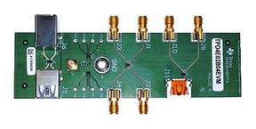
The EVM contains five TPD4E02B04DQA’s. One TPD4E02B04DQA (U1) is configured with two end-
launch SMA connectors (J9 & J10) for capturing Eye Diagrams through an HDMI Type A port (J11). The
D2 data lines are connected to two of the TPD4E02B04DQA’s IO protection pins. Another
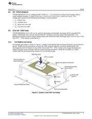
TPD4E02B04DQA (U2) is configured with 4 end-launch SMA (J1 – J4) connectors to use for 4-port
analysis with a vector network analyzer. Two TPD4E02B04DQA’s (U3 & U4) are configured with test
points for striking ESD to the protection pins, U3 also has an SMB (J7) connector for capturing a clamping
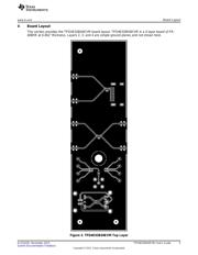
waveform with an oscilloscope during an ESD test. Caution must be taken when capturing clamping
waveforms during an ESD event so as not to damage the oscilloscope. A proper procedure is outlined
below in the Section 3.4 section. One TPD4E02B04DQA (U5) is configured to protect the Super-Speed
lines between a USB 3.1 Type A (J5) and a USB 3.1 Type B (J6) connector.
Table 1. EVM Configuration
Reference Designator TI Part Number Configuration
U1 TPD4E02B04DQA HDMI 2.0 Eye Diagram
U2 TPD4E02B04DQA S-parameters
U3 – U4 TPD4E02B04DQA IEC61000-4-2 ESD Tests
U3 TPD4E02B04DQA ESD Clamping waveforms
U5 TPD4E02B04DQA USB 3.1 Eye Diagram
2 Definitions
Contact Discharge — a method of testing in which the electrode of the ESD simulator is held in contact
with the device-under-test (DUT).
Air Discharge — a method of testing in which the charged electrode of the ESD simulator approaches
the DUT, and a spark to the DUT actuates the discharge.
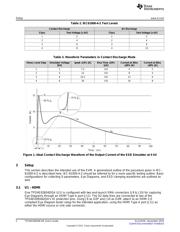
ESD simulator — a device that outputs IEC61000-4-2 compliance ESD waveforms shown in Figure 1
with adjustable ranges shown in Table 2 and Table 3.
IEC61000-4-2 has 4 classes of protection levels. Classes 1 – 4 are shown in Table 2. Stress tests
should be incrementally tested to level 4 as shown in Table 3 until the point of failure. If the DUT
does not fail at 8 kV, testing can continue in 2 kV increments until failure.
1
SLVUAH6–November 2015 TPD4E02B04EVM User's Guide
Submit Documentation Feedback
Copyright © 2015, Texas Instruments Incorporated
器件 Datasheet 文档搜索
AiEMA 数据库涵盖高达 72,405,303 个元件的数据手册,每天更新 5,000 多个 PDF 文件
