Datasheet 搜索 > 开发板 > TI(德州仪器) > TPS62140EVM-505 数据手册 > TPS62140EVM-505 产品设计参考手册 1/23 页


¥ 422.913
TPS62140EVM-505 产品设计参考手册 - TI(德州仪器)
制造商:
TI(德州仪器)
分类:
开发板
描述:
TEXAS INSTRUMENTS TPS62140EVM-505 评估模块, TPS62140EVM-505
Pictures:
3D模型
符号图
焊盘图
引脚图
产品图
页面导航:
原理图在P17P18
应用领域在P22P23
导航目录
TPS62140EVM-505数据手册
Page:
of 23 Go
若手册格式错乱,请下载阅览PDF原文件
User's Guide
SLVU437A–October 2011–Revised July 2013
TPS62130EVM-505, TPS62140EVM-505, and
TPS62150EVM-505 Evaluation Modules
This user’s guide describes the characteristics, operation, and use of the Texas Instruments TPS62130,
TPS62140, and TPS62150 evaluation modules (EVM). These EVMs are designed to help the user easily
evaluate and test the operation and functionality of the TPS62130, TPS62140, and TPS62150. This user’s
guide includes setup instructions for the hardware, printed-circuit board layouts for the EVMs, a schematic
diagram, a bill of materials, and test results for the EVMs. After the release of the A-version devices in the
summer of 2013, these EVMs are assembled with the TPS62130A, TPS62140A, or TPS62150A.
Contents
1 Introduction .................................................................................................................. 2
2 Setup ......................................................................................................................... 3
3 TPS621x0EVM-505 Test Results ......................................................................................... 4
4 Board Layout ............................................................................................................... 13
5 Schematic and Bill of Materials .......................................................................................... 17
List of Figures
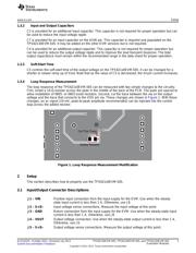
1 Loop Response Measurement Modification............................................................................. 3
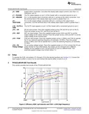
2 Efficiency With 1-µH Inductor and FSW = LOW (high frequency).................................................... 4
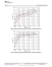
3 Efficiency With 2.2-µH Inductor and FSW = LOW (high frequency) ................................................. 5
4 Efficiency With 2.2-µH Inductor and FSW = HIGH (low frequency).................................................. 5
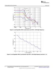
5 Load Regulation With 2.2-µH Inductor and FSW = LOW (high frequency) ......................................... 6
6 Line Regulation With 2.2-µH Inductor and FSW = LOW (high frequency) and Iout = 1 A ........................ 6
7 Loop Response With 2.2-µH Inductor and FSW = LOW (high frequency) and V
IN
= 12 V and I
OUT
= 1 A ...... 7
8 Input Voltage Ripple With 2.2-µH Inductor and FSW = LOW (high frequency) and Vin = 12 V and Iout =
1 A ............................................................................................................................ 7
9 Output Voltage Ripple With 2.2-µH Inductor and FSW = LOW (high frequency) and Vin = 12 V and Iout =
1 A ............................................................................................................................ 8
10 Output Voltage Ripple With 2.2-µH Inductor and FSW = HIGH (low frequency) and Vin = 12 V and Iout =
1 A ............................................................................................................................ 8
11 Load Transient Response With 1-µH Inductor and Vin = 12 V ....................................................... 9
12 Load Transient Response With 2.2-µH Inductor and Vin = 12 V..................................................... 9
13 Start-Up on EN with 1 A Load and Vin = 12 V ........................................................................ 10
14 Shutdown on EN with 1 A Load and Vin = 12 V ...................................................................... 10
15 TPS62130 Prebias Start-Up and Shutdown on EN With 1-A Load and Vin = 12 V .............................. 11
16 TPS62130A Prebias Start-Up and Shutdown on EN With 1-A Load and Vin = 12 V ............................ 11
17 Thermal Performance With 1-µH Inductor and Vin = 12 V and Iout = 3 A and FSW = LOW (high
frequency) .................................................................................................................. 12
18 Thermal Performance With 2.2-µH Inductor Vin = 12 V and Iout = 3 A and FSW = HIGH (low
frequency) .................................................................................................................. 13
19 Assembly Layer............................................................................................................ 14
20 Top Layer Routing......................................................................................................... 14
21 Internal Layer-1 Routing.................................................................................................. 15
22 Internal Layer-2 Routing.................................................................................................. 15
23 Bottom Layer Routing..................................................................................................... 16
1
SLVU437A–October 2011–Revised July 2013 TPS62130EVM-505, TPS62140EVM-505, and TPS62150EVM-505
Evaluation Modules
Submit Documentation Feedback
Copyright © 2011–2013, Texas Instruments Incorporated
器件 Datasheet 文档搜索
AiEMA 数据库涵盖高达 72,405,303 个元件的数据手册,每天更新 5,000 多个 PDF 文件
