Datasheet 搜索 > 微控制器 > ATMEL(爱特美尔) > ATMEGA128-16MU 数据手册 > ATMEGA128-16MU 用户编程技术手册 6/386 页

¥ 7.184
ATMEGA128-16MU 用户编程技术手册 - ATMEL(爱特美尔)
制造商:
ATMEL(爱特美尔)
分类:
微控制器
封装:
VFQFN-64
描述:
8 位 megaAVR® 微控制器,32KB 到 256KB 闪存,Atmel我们在 RS Components 提供多款来自 Atmel 的 megaAVR 8 位微控制器。 每个微控制器均基于增强型 RISC 体系结构,并具有 QTouch 库支持。 所有微控制器类型具有不同 Kb 的系统内可编程内存、EEPROM 和 SRAM 以及不同引脚和封装类型。 **megaAVR 8 位微控制器类型** ATmega32 ATmega64 ATmega128 ATmega324 ATmega325 ATmega406 ATmega640 ATmega644 ATmega645 ATmega1280 ATmega1281 ATmega1284 ATmega2560 ATmega2561 ATmega3250 ATmega6450### AVR 微控制器,Atmel
Pictures:
3D模型
符号图
焊盘图
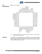
引脚图
产品图
页面导航:
引脚图在P2P5P68P93P112P146Hot
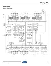
原理图在P3P10P66P93P94P96P97P113P118P119P121P123
封装尺寸在P369P370
型号编码规则在P368P374P375P376P378
封装信息在P369P376
应用领域在P34P50P61P64P273P276P284P286P287
电气规格在P90P375
导航目录
ATMEGA128-16MU数据手册
Page:
of 386 Go
若手册格式错乱,请下载阅览PDF原文件

6
2467S–AVR–07/09
ATmega128
resistors are activated. The Port C pins are tri-stated when a reset condition becomes active,
even if the clock is not running.
Port C also serves the functions of special features of the ATmega128 as listed on page 77. In
ATmega103 compatibility mode, Port C is output only, and the port C pins are not tri-stated
when a reset condition becomes active.
Note: The ATmega128 is by default shipped in ATmega103 compatibility mode. Thus, if the parts are not
programmed before they are put on the PCB, PORTC will be output during first power up, and until
the ATmega103 compatibility mode is disabled.
Port D (PD7..PD0) Port D is an 8-bit bi-directional I/O port with internal pull-up resistors (selected for each bit). The
Port D output buffers have symmetrical drive characteristics with both high sink and source
capability. As inputs, Port D pins that are externally pulled low will source current if the pull-up
resistors are activated. The Port D pins are tri-stated when a reset condition becomes active,
even if the clock is not running.
Port D also serves the functions of various special features of the ATmega128 as listed on page
78.
Port E (PE7..PE0) Port E is an 8-bit bi-directional I/O port with internal pull-up resistors (selected for each bit). The
Port E output buffers have symmetrical drive characteristics with both high sink and source
capability. As inputs, Port E pins that are externally pulled low will source current if the pull-up
resistors are activated. The Port E pins are tri-stated when a reset condition becomes active,
even if the clock is not running.
Port E also serves the functions of various special features of the ATmega128 as listed on page
81.
Port F (PF7..PF0) Port F serves as the analog inputs to the A/D Converter.
Port F also serves as an 8-bit bi-directional I/O port, if the A/D Converter is not used. Port pins
can provide internal pull-up resistors (selected for each bit). The Port F output buffers have sym-
metrical drive characteristics with both high sink and source capability. As inputs, Port F pins
that are externally pulled low will source current if the pull-up resistors are activated. The Port F
pins are tri-stated when a reset condition becomes active, even if the clock is not running. If the
JTAG interface is enabled, the pull-up resistors on pins PF7(TDI), PF5(TMS), and PF4(TCK) will
be activated even if a Reset occurs.
The TDO pin is tri-stated unless TAP states that shift out data are entered.
Port F also serves the functions of the JTAG interface.
In ATmega103 compatibility mode, Port F is an input Port only.
Port G (PG4..PG0) Port G is a 5-bit bi-directional I/O port with internal pull-up resistors (selected for each bit). The
Port G output buffers have symmetrical drive characteristics with both high sink and source
capability. As inputs, Port G pins that are externally pulled low will source current if the pull-up
resistors are activated. The Port G pins are tri-stated when a reset condition becomes active,
even if the clock is not running.
Port G also serves the functions of various special features.
The port G pins are tri-stated when a reset condition becomes active, even if the clock is not
running.
In ATmega103 compatibility mode, these pins only serves as strobes signals to the external
memory as well as input to the 32 kHz Oscillator, and the pins are initialized to PG0 = 1, PG1 =
1, and PG2 = 0 asynchronously when a reset condition becomes active, even if the clock is not
running. PG3 and PG4 are oscillator pins.
器件 Datasheet 文档搜索
AiEMA 数据库涵盖高达 72,405,303 个元件的数据手册,每天更新 5,000 多个 PDF 文件
