Datasheet 搜索 > 开发套件 > ATMEL(爱特美尔) > ATMEGA1284P-XPLD 数据手册 > ATMEGA1284P-XPLD 用户编程技术手册 6/659 页

¥ 277.295
ATMEGA1284P-XPLD 用户编程技术手册 - ATMEL(爱特美尔)
制造商:
ATMEL(爱特美尔)
分类:
开发套件
描述:
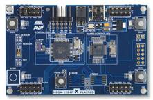
ATMEGA1284P-XPLD XPlained 评估套件ATMEGA1284P-XPLD XPlained 评估套件设计用于评估 ATmega1284 微控制器,其具有许多板载特征,如 **QTouch®** 按钮。 **XPlained Pro** 平台的有益特点是集成 **Atmel Studio**,包含 Atmel 软件框架驱动器和演示代码,并支持流数据。 应用包括移动设备(相机、电话、平板电脑和笔记本电脑)、智能仪表、家用电器、远程控制和工业自动化中的感应。 **ATMEGA1284P-XPLD 的功能和优点** ATmega1284P MCU AT32UC3B1256 MCU QTouch® 按钮 ADC,带光传感器和温度传感器 4 个 LED 3 个按钮 RC 滤波器 连接管座 USB 供电### AVR 微控制器,Atmel
Pictures:
3D模型
符号图
焊盘图
引脚图
产品图
页面导航:
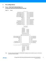
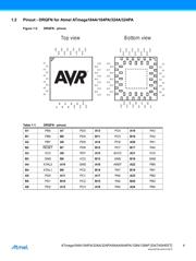
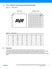
引脚图在P3P7P91P107P138Hot
原理图在P6P10P255P650
封装尺寸在P643P644P645P646P647
型号编码规则在P635P636P637P638P639P640P641P642P651
封装信息在P643
应用领域在P40P50P62P66P269P273P287P288P659
电气规格在P72
导航目录
ATMEGA1284P-XPLD数据手册
Page:
of 659 Go
若手册格式错乱,请下载阅览PDF原文件

6
ATmega164A/164PA/324A/324PA/644A/644PA/1284/1284P [DATASHEET]
Atmel-8272G-AVR-01/2015
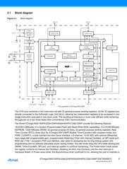
2.1 Block diagram
Figure 2-1. Block diagram.
The AVR core combines a rich instruction set with 32 general purpose working registers. All the 32 registers are
directly connected to the Arithmetic Logic Unit (ALU), allowing two independent registers to be accessed in one
single instruction executed in one clock cycle. The resulting architecture is more code efficient while achieving
throughputs up to ten times faster than conventional CISC microcontrollers.
The Atmel ATmega164A/164PA/324A/324PA/644A/644PA/1284/1284P provide the following features:
16/32/64/128Kbytes of In-System Programmable Flash with Read-While-Write capabilities, 512/1K/2K/4Kbytes
EEPROM, 1/2/4/16Kbytes SRAM, 32 general purpose I/O lines, 32 general purpose working registers, Real
Time Counter (RTC), three (four for ATmega1284/1284P) flexible Timer/Counters with compare modes and
PWM, 2 USARTs, a byte oriented two-wire Serial Interface, a 8-channel, 10-bit ADC with optional differential
input stage with programmable gain, programmable Watchdog Timer with Internal Oscillator, an SPI serial port,
IEEE std. 1149.1 compliant JTAG test interface, also used for accessing the On-chip Debug system and
programming and six software selectable power saving modes. The Idle mode stops the CPU while allowing the
SRAM, Timer/Counters, SPI port, and interrupt system to continue functioning. The Power-down mode saves
the register contents but freezes the Oscillator, disabling all other chip functions until the next interrupt or
Hardware Reset. In Power-save mode, the asynchronous timer continues to run, allowing the user to maintain a
CPU
GND
VCC
RESET
Power
Supervision
POR / BOD &
RESET
Watchdog
Oscillator
Watchdog
Timer
Oscillator
Circuits /
Clock
Generation
XTAL1
XTAL2
PORT A (8)
PORT D (8)
PD7..0
PORT C (8)
PC5..0
TWI
SPI
EEPROM
JTAG/OCD
16bit T/C 1
8bit T/C 2
8bit T/C 0
SRAMFLASH
USART 0
Internal
Bandgap reference
Analog
Comparator
A/D
Converter
PA7..0
PORT B (8)
PB7..0
USART 1
TOSC1/PC6TOSC2/PC7
16bit T/C 1
16bit T/C 3*
* Only available in ATmega1284/1284P
器件 Datasheet 文档搜索
AiEMA 数据库涵盖高达 72,405,303 个元件的数据手册,每天更新 5,000 多个 PDF 文件
