Datasheet 搜索 > 微控制器 > Microchip(微芯) > ATMEGA8535-16MU 数据手册 > ATMEGA8535-16MU 用户编程技术手册 4/321 页

 器件3D模型
¥ 9.297
ATMEGA8535-16MU 用户编程技术手册 - Microchip(微芯)
制造商:
Microchip(微芯)
分类:
微控制器
封装:
VQFN-44
Pictures:
3D模型
符号图
焊盘图
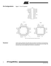
引脚图
产品图
页面导航:
引脚图在P2P5P53Hot
原理图在P3P8P51P71P72P73P75P90P95P96P98P100
封装尺寸在P306P307P308P309
型号编码规则在P304
封装信息在P306P312
技术参数、封装参数在P312
应用领域在P36P46P49P224P227P237P238
电气规格在P51P312

导航目录
ATMEGA8535-16MU数据手册
Page:
of 321 Go
若手册格式错乱,请下载阅览PDF原文件

4
ATmega8535(L)
2502K–AVR–10/06
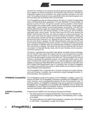
The AVR core combines a rich instruction set with 32 general purpose working registers.
All 32 registers are directly connected to the Arithmetic Logic Unit (ALU), allowing two
independent registers to be accessed in one single instruction executed in one clock
cycle. The resulting architecture is more code efficient while achieving throughputs up to
ten times faster than conventional CISC microcontrollers.
The ATmega8535 provides the following features: 8K bytes of In-System Programmable
Flash with Read-While-Write capabilities, 512 bytes EEPROM, 512 bytes SRAM, 32
general purpose I/O lines, 32 general purpose working registers, three flexible
Timer/Counters with compare modes, internal and external interrupts, a serial program-
mable USART, a byte oriented Two-wire Serial Interface, an 8-channel, 10-bit ADC with
optional differential input stage with programmable gain in TQFP package, a program-
mable Watchdog Timer with Internal Oscillator, an SPI serial port, and six software
selectable power saving modes. The Idle mode stops the CPU while allowing the
SRAM, Timer/Counters, SPI port, and interrupt system to continue functioning. The
Power-down mode saves the register contents but freezes the Oscillator, disabling all
other chip functions until the next interrupt or Hardware Reset. In Power-save mode, the
asynchronous timer continues to run, allowing the user to maintain a timer base while
the rest of the device is sleeping. The ADC Noise Reduction mode stops the CPU and
all I/O modules except asynchronous timer and ADC, to minimize switching noise during
ADC conversions. In Standby mode, the crystal/resonator Oscillator is running while the
rest of the device is sleeping. This allows very fast start-up combined with low-power
consumption. In Extended Standby mode, both the main Oscillator and the asynchro-
nous timer continue to run.
The device is manufactured using Atmel’s high density nonvolatile memory technology.
The On-chip ISP Flash allows the program memory to be reprogrammed In-System
through an SPI serial interface, by a conventional nonvolatile memory programmer, or
by an On-chip Boot program running on the AVR core. The boot program can use any
interface to download the application program in the Application Flash memory. Soft-
ware in the Boot Flash section will continue to run while the Application Flash section is
updated, providing true Read-While-Write operation. By combining an 8-bit RISC CPU
with In-System Self-Programmable Flash on a monolithic chip, the Atmel ATmega8535
is a powerful microcontroller that provides a highly flexible and cost effective solution to
many embedded control applications.
The ATmega8535 AVR is supported with a full suite of program and system develop-
ment tools including: C compilers, macro assemblers, program debugger/simulators, In-
Circuit Emulators, and evaluation kits.
AT90S8535 Compatibility The ATmega8535 provides all the features of the AT90S8535. In addition, several new
features are added. The ATmega8535 is backward compatible with AT90S8535 in most
cases. However, some incompatibilities between the two microcontrollers exist. To
solve this problem, an AT90S8535 compatibility mode can be selected by programming
the S8535C fuse. ATmega8535 is pin compatible with AT90S8535, and can replace the
AT90S8535 on current Printed Circuit Boards. However, the location of fuse bits and the
electrical characteristics differs between the two devices.
AT90S8535 Compatibility
Mode
Programming the S8535C fuse will change the following functionality:
• The timed sequence for changing the Watchdog Time-out period is disabled. See
“Timed Sequences for Changing the Configuration of the Watchdog Timer” on page
45 for details.
• The double buffering of the USART Receive Register is disabled. See “AVR USART
vs. AVR UART – Compatibility” on page 146 for details.
器件 Datasheet 文档搜索
AiEMA 数据库涵盖高达 72,405,303 个元件的数据手册,每天更新 5,000 多个 PDF 文件
