Datasheet 搜索 > 微控制器 > Microchip(微芯) > ATMEGA8U2-MU 数据手册 > ATMEGA8U2-MU 用户编程技术手册 1/24 页

 器件3D模型
¥ 21.443
ATMEGA8U2-MU 用户编程技术手册 - Microchip(微芯)
制造商:
Microchip(微芯)
分类:
微控制器
封装:
QFN-32
描述:
8 位 megaAVR 微控制器,带 USB 控制器,Atmel这些 megaAVR® 微控制器具有 USB 控制器,并且可以提供大量程序和数据内存,性能高达 20 MIPS。 所有 megaAVR 均提供自动编程功能,可实现快速、安全、经济实惠的在线升级。对不起 您的请求暂时未被执行 | ---|---
Pictures:
3D模型
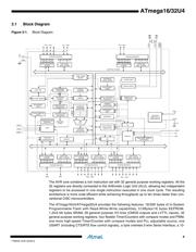
符号图
焊盘图
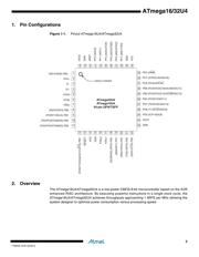
引脚图
产品图
页面导航:
导航目录
ATMEGA8U2-MU数据手册
Page:
of 24 Go
若手册格式错乱,请下载阅览PDF原文件

Features
• High Performance, Low Power AVR
®
8-Bit Microcontroller
• Advanced RISC Architecture
– 135 Powerful Instructions – Most Single Clock Cycle Execution
– 32 x 8 General Purpose Working Registers
– Fully Static Operation
– Up to 16 MIPS Throughput at 16 MHz
– On-Chip 2-cycle Multiplier
• Non-volatile Program and Data Memories
– 16/32K Bytes of In-System Self-Programmable Flash (ATmega16U4/ATmega32U4)
– 1.25/2.5K Bytes Internal SRAM (ATmega16U4/ATmega32U4)
– 512Bytes/1K Bytes Internal EEPROM (ATmega16U4/ATmega32U4)
– Write/Erase Cycles: 10,000 Flash/100,000 EEPROM
– Data retention: 20 years at 85C/ 100 years at 25C
(1)
– Optional Boot Code Section with Independent Lock Bits
In-System Programming by On-chip Boot Program
True Read-While-Write Operation
All supplied parts are preprogramed with a default USB bootloader
– Programming Lock for Software Security
• JTAG (IEEE std. 1149.1 compliant) Interface
– Boundary-scan Capabilities According to the JTAG Standard
– Extensive On-chip Debug Support
– Programming of Flash, EEPROM, Fuses, and Lock Bits through the JTAG Interface
• USB 2.0 Full-speed/Low Speed Device Module with Interrupt on Transfer Completion
– Complies fully with Universal Serial Bus Specification Rev 2.0
– Supports data transfer rates up to 12 Mbit/s and 1.5 Mbit/s
– Endpoint 0 for Control Transfers: up to 64-bytes
– 6 Programmable Endpoints with IN or Out Directions and with Bulk, Interrupt or
Isochronous Transfers
– Configurable Endpoints size up to 256 bytes in double bank mode
– Fully independent 832 bytes USB DPRAM for endpoint memory allocation
– Suspend/Resume Interrupts
– CPU Reset possible on USB Bus Reset detection
– 48 MHz from PLL for Full-speed Bus Operation
– USB Bus Connection/Disconnection on Microcontroller Request
– Crystal-less operation for Low Speed mode
• Peripheral Features
– On-chip PLL for USB and High Speed Timer: 32 up to 96 MHz operation
– One 8-bit Timer/Counter with Separate Prescaler and Compare Mode
– Two 16-bit Timer/Counter with Separate Prescaler, Compare- and Capture Mode
– One 10-bit High-Speed Timer/Counter with PLL (64 MHz) and Compare Mode
– Four 8-bit PWM Channels
– Four PWM Channels with Programmable Resolution from 2 to 16 Bits
– Six PWM Channels for High Speed Operation, with Programmable Resolution from
2 to 11 Bits
– Output Compare Modulator
– 12-channels, 10-bit ADC (features Differential Channels with Programmable Gain)
– Programmable Serial USART with Hardware Flow Control
– Master/Slave SPI Serial Interface
8-bit
Microcontroller
with
16/32K Bytes of
ISP Flash
and USB
Controller
ATmega16U4
ATmega32U4
Preliminary
Summary
7766GS–AVR–02/2014
器件 Datasheet 文档搜索
AiEMA 数据库涵盖高达 72,405,303 个元件的数据手册,每天更新 5,000 多个 PDF 文件
