Datasheet 搜索 > USB芯片 > FTDI Chip(飞特帝亚) > FT4222HQ-R 数据手册 > FT4222HQ-R 用户编程技术手册 5/21 页
 器件3D模型
¥ 11.059
FT4222HQ-R 用户编程技术手册 - FTDI Chip(飞特帝亚)
制造商:
FTDI Chip(飞特帝亚)
分类:
USB芯片
封装:
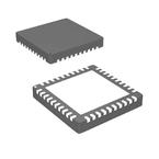
VQFN-32
Pictures:
3D模型
符号图
焊盘图
引脚图
产品图
页面导航:
引脚图在P5Hot


导航目录
FT4222HQ-R数据手册
Page:
of 21 Go
若手册格式错乱,请下载阅览PDF原文件

Copyright © 2008 Future Technology Devices International Limited 4
Document Reference No.: FT_000078
FTDI Device EEPROM Programming Using a Vinculum VNC1L Application Note AN_105
Version 1.00
Clearance No.:
FTDI# 59
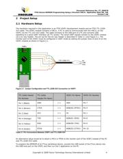
2 Project Setup
2.1 Hardware Setup
The hardware required in this application is an FTDI VDIP1 development module and an FTDI TTL-232R-
3V3 cable. The VDIP1 module contains a VNC1L. A PC is used to communicate with the VNC1L on the
VDIP1 via the TTL-232-3V3 cable. The cable connects to the USB port of a PC and converts USB
signalling to a serial UART interface (at TTL levels). The serial UART signals connect to the VDIP1 module
via a six way header. The pin out for the six way header is described in Table 2.1 and Figure 2.1. The
monitor port of the VDIP1 must be configured in UART mode by setting the jumper links J3 and J4 on the
VDIP1 module as shown in Figure 2.1.
Figure 2.1 Jumper Configuration and TTL-232R-3V3 Connection on VDIP1
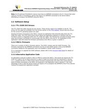
TTL Cable Header
Pin Number
TTL Cable
Header Pin Name
VDIP1 Pin Name VDIP1 Pin Number
Pin 1 (Black)
GND <-> GND Pin 7
Pin 2 (Brown)
CTS# <-> ADBUS2 (RTS#) Pin 9
Pin 3 (Red)
VCC <-> 5V Pin 1
Pin 4 (Orange)
TXD <-> ADBUS1 (RXD) Pin 8
Pin 5 (Yellow)
RXD <-> ADBUS0 (TXD) Pin 6
Pin 6 (Green)
RTS# <-> ADBUS3 (CTS#) Pin 10
Table 2.1 Pin Connections Between VDIP1 and TTL-232R-3V3
An alternative setup would be to attach a MCU or FPGA to the monitor port of the VDIP1 instead of the PC
and TTL-232R-3V3 cable.
To program the EEPROM of an FTxxx peripheral device, connect the USB socket of the FTxxx device into
the USB host port on the VDIP1 and then run the C application on the PC.
器件 Datasheet 文档搜索
AiEMA 数据库涵盖高达 72,405,303 个元件的数据手册,每天更新 5,000 多个 PDF 文件
