Datasheet 搜索 > 微控制器 > NXP(恩智浦) > LPC1343FBD48,151 数据手册 > LPC1343FBD48,151 用户编程技术手册 3/17 页
 器件3D模型
¥ 36.53
LPC1343FBD48,151 用户编程技术手册 - NXP(恩智浦)
制造商:
NXP(恩智浦)
分类:
微控制器
封装:
LQFP-48
描述:
ARM Cortex-M3 Microcontrollers, NXP基于 NXP ARM Cortex-M3 的微控制器,适用于嵌入式应用,具有高集成水平并提供系统增强功能,例如低功耗、增强调试功能和更高级别的块集成支持。Cortex-M3 核可最高以 150 MHz 运行 高达 512KB 的闪存和高达 64KB 的片上 SRAM 低功耗,用于 LPC13xx 设备时低至 200μA/MHz 新唤醒中断控制器 (WIC)、套放向量中断控制器 (NVIC) 和存储器保护装置 配有先进的外围设备,如以太网、USB 主机/OTG/设备、CAN、IS、快速模式 Plus (Fm+) IC、12 位 ADC、电机控制 PWM、正交编码器接口和其他。 ### ARM Cortex 微控制器,NXP
Pictures:
3D模型
符号图
焊盘图
引脚图
产品图
页面导航:
应用领域在P13P16
导航目录
LPC1343FBD48,151数据手册
Page:
of 17 Go
若手册格式错乱,请下载阅览PDF原文件

NXP Semiconductors
AN10986
USB In-System Programming with the LPC1300
1. Introduction
The LPC1300 microcontroller family is based on the ARM Cortex-M3 CPU architecture
for embedded applications featuring a high level of support block integration and low
power consumption. The peripheral complement of the LPC1300 series includes up to
32 kB of flash memory, up to 8 kB of data memory, USB Device interface, 1 UART, 1
SSP controller, SPI interface, I2C interface, 8 channel 10-bit ADC, 4 general purpose
timer/PWMs, and up to 40 general purpose I/O pins.
Also present is an on-chip ROM containing In-System Programming capability (a
bootloader) supporting UART and USB flash programming, as well as APIs for user
code. The flash API implements a simple interface to the on-board flash programming
functionality and allows entry to ISP mode at any time. The USB API supports
development of Human Interface Devices (HID) and Mass Storage Class (MSC) devices
without requiring driver code to be written by the customer or stored in Flash.
The various topics covered in this application note are as follows:
1. USB In-System Programming Overview
2. USB ISP Details
3. Automating USB ISP
4. Automating entry of USB ISP
5. Sample Software
6. Conclusion
2. USB In-System Programming (ISP) Overview
The LPC1300’s on-chip USB ISP firmware enables programming and updating of
firmware in the field by end users using standard personal computer operating systems.
This document will reference the LPC1343 in particular, but the procedures should also
apply to other LPC1300 family products with on-chip USB.
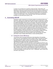
Holding PIO0_1 low during power-up will trigger the on-chip ISP firmware to enter ISP
mode (unless it is disabled by the NO_ISP code read protection [CRP] mode). Once ISP
mode has been entered, the USB VBUS line PIO0_3 is checked. If high, then USB ISP
will be entered. If low, UART ISP will be entered instead. The diagram in the User’s
Manual titled “Boot Process Flowchart” explains this process in greater detail.
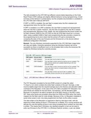
Upon entry to USB ISP mode, the LPC1300 part will enable the on-chip USB full-speed
interface as a mass storage class device. This disk device will contain a FAT12
filesystem which will appear as a standard disk device in most operating systems. The
label of the disk will indicate the CRP status and the disk will contain a single file,
firmware.bin. Deleting and rewriting this file will write to the flash memory if allowed by
the code protect settings. Reading the contents of flash memory is as simple as copying
the firmware.bin file.
AN10986 All information provided in this document is subject to legal disclaimers. © NXP B.V. 2010. All rights reserved.
Application note Rev. 1 — 24 September 2010 3 of 17
器件 Datasheet 文档搜索
AiEMA 数据库涵盖高达 72,405,303 个元件的数据手册,每天更新 5,000 多个 PDF 文件
