Datasheet 搜索 > 接口芯片 > NXP(恩智浦) > PCA9554ADB,118 数据手册 > PCA9554ADB,118 用户编程技术手册 1/27 页
 器件3D模型
¥ 2.02
PCA9554ADB,118 用户编程技术手册 - NXP(恩智浦)
制造商:
NXP(恩智浦)
分类:
接口芯片
封装:
SSOP-16
描述:
8位I2C总线和中断的SMBus I / O端口 8-bit I2C-bus and SMBus I/O port with interrupt
Pictures:
3D模型
符号图
焊盘图
引脚图
产品图
页面导航:
导航目录
PCA9554ADB,118数据手册
Page:
of 27 Go
若手册格式错乱,请下载阅览PDF原文件

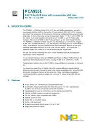
1. General description
The PCA9551 LED blinker blinks LEDs in I
2
C-bus and SMBus applications where it is
necessary to limit bus traffic or free up the I
2
C-bus master's (MCU, MPU, DSP, chip set,
etc.) timer. The uniqueness of this device is the internal oscillator with two programmable
blink rates. To blink LEDs using normal I/O expanders like the PCF8574 or PCA9554, the
bus master must send repeated commands to turn the LED on and off. This greatly
increases the amount of traffic on the I
2
C-bus and uses up one of the master's timers.
The PCA9551 LED blinker instead requires only the initial set-up command to program
BLINK RATE 1 and BLINK RATE 2 (i.e., the frequency and duty cycle) for each individual
output. From then on, only one command from the bus master is required to turn each
individual open-drain output on, off, or to cycle at BLINK RATE 1 or BLINK RATE 2.
Maximum output sink current is 25 mA per bit and 100 mA per package.
Any bits not used for controlling the LEDs can be used for General Purpose parallel
Input/Output (GPIO) expansion.
The active LOW hardware reset pin (RESET) and Power-On Reset (POR) initializes the
registers to their default state, all zeroes, causing the bits to be set HIGH (LED off).
Three hardware address pins on the PCA9551 allow eight devices to operate on the same
bus.
The newer Fast-mode Plus PCA9634 8-bit LED controller offers an individual PWM
dimming control for each channel for better color mixing capabilities with a global PWM for
dimming or blinking all channels at the same time. There are 126 possible address
combinations and the maximum output sink current is 25 mA per bit and 200 mA per
package.
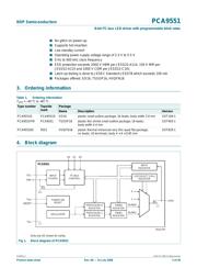
2. Features
n 8 LED drivers (on, off, flashing at a programmable rate)
n 2 selectable, fully programmable blink rates (frequency and duty cycle) between
0.148 Hz and 38 Hz (6.74 seconds and 0.026 seconds)
n Input/outputs not used as LED drivers can be used as regular GPIOs
n Internal oscillator requires no external components
n I
2
C-bus interface logic compatible with SMBus
n Internal power-on reset
n Noise filter on SCL/SDA inputs
n Active LOW reset input
n 8 open-drain outputs directly drive LEDs to 25 mA
n Edge rate control on outputs
PCA9551
8-bit I
2
C-bus LED driver with programmable blink rates
Rev. 08 — 31 July 2008 Product data sheet
器件 Datasheet 文档搜索
AiEMA 数据库涵盖高达 72,405,303 个元件的数据手册,每天更新 5,000 多个 PDF 文件
