Datasheet 搜索 > 微控制器 > Microchip(微芯) > PIC16C54C-04/P 数据手册 > PIC16C54C-04/P 用户编程技术手册 5/14 页

¥ 18.751
PIC16C54C-04/P 用户编程技术手册 - Microchip(微芯)
制造商:
Microchip(微芯)
分类:
微控制器
封装:
PDIP-18
描述:
MICROCHIP PIC16C54C-04/P 微控制器, 8位, 一次性可编程, PIC16C5xx, 4 MHz, 768 Byte, 25 Byte, 18 引脚, DIP
Pictures:
3D模型
符号图
焊盘图
引脚图
产品图
页面导航:
引脚图在P1Hot
电气规格在P11

导航目录
PIC16C54C-04/P数据手册
Page:
of 14 Go
若手册格式错乱,请下载阅览PDF原文件

1996 Microchip Technology Inc. DS30190F-page 5
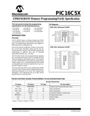
EPROM/ROM Memory Programming/Verify Specification
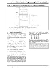
FIGURE 1-2: PIC16C5X SERIES PROGRAM MEMORY MAP IN PROGRAM/VERIFY MODE
Address
(Hex) 000
Bit Number
11 0
NNN
TTT
TTT + 1
TTT + 2
TTT + 3
TTT + 3F
(FFF)
For Customer Use
(4 x 4 bit usable)
For Factory Use
Configuration Word 4 bit
0 0 ID0
0 0 ID1
0 0 ID2
0 0 ID3
User Program Memory
(NNN + 1) x 12 bit
NNN Highest normal EPROM memory address. NNN = 0x1FF for PIC16C54, 54A, 55.
NNN = 0x3FF for PIC16C56 and 0x7FF for PIC16C57, 58A .
TTT Start address of special EPROM area and ID Locations.
1.6 Special Memor
y Locations
The ID Locations area is only enabled if the device is in
a test or programming/verify mode. Thus, in normal
operation mode only the memory location 0x000 to
0xNNN will be accessed and the Program Counter will
just roll over from address 0xNNN to 0x000 when incre-
mented.
The configuration word can only be accessed immedi-
ately after MCLR
going from V
IL
to V
HH
. The Program
Counter will be set to all '1's upon MCLR
= V
IL
. Thus,
it has the value “0xFFF” when accessing the configura-
tion EPROM. Incrementing the Program Counter once
by pulsing OSC1 causes the Program Counter to roll
over to all '0's. Incrementing the Program Counter 4K
times after reset (MCLR
= V
IL
) does not allow access to
the configuration EPROM.
1.6.1 CUSTOMER ID CODE LOCATIONS
Per definition, the first four words (address TTT to TTT
+ 3) are reserved for customer use. It is recommended
that the customer use only the four lower order bits (bits
0 through 3) of each word and filling the eight higher
order bits with '0's.
A user may want to store an identification code (ID) in
the ID locations and still be able to read this code after
the code protection bit was programmed. This is pos-
sible if the ID code is only four bits long per memory
location, is located in the least significant nibble bound-
ary of the 12-bit word, and the remaining eight bits are
all '0's.
EXAMPLE 1: CUSTOMER CODE 0xD1E2
The Customer ID code “0xD1E2” should be stored in
the ID locations 200-203 like this:
200: 0000 0000 1101
201: 0000 0000 0001
202: 0000 0000 1110
203: 0000 0000 0010
Reading these four memory locations, even with the
code protection bit programmed would still output on
Port A the bit sequence “1101”, “0001”, “1110”, “0010”
which is “0xD1E2”.
Note:
Microchip will assign a unique pattern
number for QTP and SQTP requests and
for ROM devices. This pattern number will
be unique and traceable to the submitted
code.
器件 Datasheet 文档搜索
AiEMA 数据库涵盖高达 72,405,303 个元件的数据手册,每天更新 5,000 多个 PDF 文件
