Datasheet 搜索 > 微控制器 > Microchip(微芯) > PIC16C55A-04/P 数据手册 > PIC16C55A-04/P 用户编程技术手册 6/14 页
 器件3D模型
¥ 22.541
PIC16C55A-04/P 用户编程技术手册 - Microchip(微芯)
制造商:
Microchip(微芯)
分类:
微控制器
封装:
PDIP-28
描述:
PIC16C5x 8 位微控制器Microchip 的 PIC16C 系列微控制器 8 位 CMOS MCU,将 Microchip 的 PIC® 体系架构融入到引脚和封装选件中,从节省空间的 14 引脚设备到功能丰富的 64 引脚设备。 现在由基于闪存的型号代替,这些设备在传统设计方面也仍受到欢迎。 对于新应用,应考虑 PIC16F 型号。 PIC16C5x 系列微控制器基于 Microchip 基线体系结构,带 2 层硬件堆栈和 33 个 12 位指令。 这些 MCU 提供高达 10 MIPS、3 字节程序内存和高达 73 字节 RAM 的数据存储器。 板载是一个 RC 振荡器,精确度为 ±1%。### 特点33 个指令 2 级硬件堆栈 除 PIC16C55/C55A/C57/C57C/CR57C 之外的所有型号上均有 12 个输入/输出引脚 20 个输入/输出引脚 – PIC16C55/C55A/C57/C57C/CR57C 一个 8 位计时器 监控计时器 (WDT) 通电重置 (POR) 设备重置计时器 (DRT) ### PIC16 微控制器
Pictures:
3D模型
符号图
焊盘图
引脚图
产品图
页面导航:
引脚图在P1Hot
电气规格在P11
导航目录
PIC16C55A-04/P数据手册
Page:
of 14 Go
若手册格式错乱,请下载阅览PDF原文件
PIC16C5X
DS30190F-page 6
1996 Microchip Technology Inc.
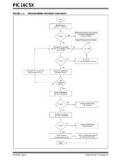
2.0 CONFIGURATION WORD
The configuration word is the very first memory location
which is accessed after entering the program/verify
mode of the PIC16C5X. It contains the two bits for the
selection of the oscillator type, the watchdog timer
enable bit, and the code protection bit. All other bits (4
through 11) are read as '1's.
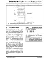
One-Time-Programmable (OTP) devices may have the
oscillator configuration bits “FOSC0” and “FOSC1” set
by the factory and are tested accordingly. The pack-
ages are marked “PIC16C5XHS”, “PIC16C5XXT”,
“PIC16C5XLP”, or “PIC16C5XRC”. Therefore, it is
essential that the inputs RA0 and RA1 are held at '1's
when programming the “WDTE” and/or the “CP” bit of
the configuration word. Otherwise, the factory tested
and selected oscillator configuration could be overwrit-
ten and the functionality of the device is not guaranteed
any more.
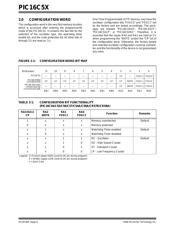
FIGURE 2-1: CONFIGURATION WORD BIT MAP
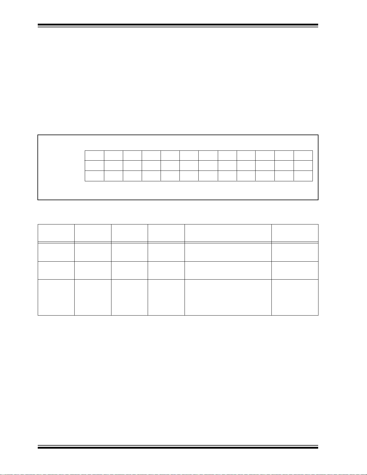
TABLE 2-1: CONFIGURATION BIT FUNCTIONALITY
(PIC16C54/C55/C56/C57/C54A/C58A/CR57B/CR58A)
RA3-RA11
CP
RA2
WDTE
RA1
FOSC1
RA0
FOSC2
Function Remarks
1 x x x Memory unprotected Default
0 x x x Memory protected
x 1 x x Watchdog Timer enabled Default
x 0 x x Watchdog Timer disabled
x x 1 1 RC - Oscillator Default
x x 1 0 HS - High Speed Crystal
x x 0 1 XT - Standard Crystal
x x 0 0 LP - Low Frequency Crystal
Legend: 1= Erased (apply HIGH Level to I/O pin during program)
0 = Written (apply LOW Level to I/O pin during program)
x = Don’t Care
Bit Number:
11
RB7
CP
10
RB6
CP
9
RB5
CP
8
RB4
CP
7
RB3
CP
6
RB2
CP
5
RB1
CP
4
RB0
CP
3
RA3
CP
2
RA2
WDTE
1
RA1
FOSC1
0
RA0
FOSC0
————————CPWDTE FOSC1 FOSC0
PIC16C54/C54A/
PIC16CR58A/
————————CP—FOSC1 FOSC0
PIC16C52
C57/CR57A/C58A
CR57B/CR54A
CR54/C55/C56/
器件 Datasheet 文档搜索
AiEMA 数据库涵盖高达 72,405,303 个元件的数据手册,每天更新 5,000 多个 PDF 文件
