Datasheet 搜索 > 8位微控制器 > Microchip(微芯) > PIC16C55-XT/SO 数据手册 > PIC16C55-XT/SO 用户编程技术手册 3/16 页
 器件3D模型
¥ 39.449
PIC16C55-XT/SO 用户编程技术手册 - Microchip(微芯)
制造商:
Microchip(微芯)
分类:
8位微控制器
封装:
SOIC-28
描述:
MICROCHIP PIC16C55-XT/SO 微控制器, 8位, 一次性可编程, PIC16C5xx, 20 MHz, 768 Byte, 24 Byte, 28 引脚, SOIC
Pictures:
3D模型
符号图
焊盘图
引脚图
产品图
页面导航:
引脚图在P1Hot
电气规格在P13


导航目录
PIC16C55-XT/SO数据手册
Page:
of 16 Go
若手册格式错乱,请下载阅览PDF原文件

1999 Microchip Technology Inc. DS30190H-page 3
PIC16C5XX
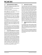
1.4 Programming Method
The programming technique is described in the follow-
ing section. It is designed to guarantee good program-
ming margins. It does, however, require a variable
power supply for V
CC.
1.4.1 PROGRAMMING METHOD DETAILS
Essentially, this technique includes the following steps:
1. Perform blank check at V
DD = VDDmin. Report
failure. The device may not be properly erased.
2. Program location with pulses and verify after
each pulse at V
DD = VDDP:
where V
DDP = VDD range required during pro-
gramming (4.75V - 5.25V).
a) Programming condition:
V
PP = 13.0V to 13.25V
V
DD = VDDP = 4.75V - 5.25V
V
PP must be ≥ VDD + 7.25V to keep “programming
mode” active.
b) Verify condition:
V
DD = VDDP
VPP ≥ VDD + 7.5V but not to exceed 13.25V
If location fails to program after “N” pulses, (sug-
gested maximum program pulses of 8) then report
error as a programming failure.
3. Once location passes “Step 2", apply 11X over-
programming, i.e., apply eleven times the num-
ber of pulses that were required to program the
location. This will guarantee a solid program-
ming margin. The overprogramming should be
made “software programmable” for easy
updates.
4. Program all locations.
5. Verify all locations (using speed verify mode) at
V
DD = VDDmin
6. Verify all locations at V
DD = VDDmax
V
DDmin is the minimum operating voltage spec. for
the part. V
DDmax is the maximum operating volt-
age spec. for the part.
1.4.2 SYSTEM REQUIREMENTS
Clearly, to implement this technique, the most stringent
requirements will be that of the power supplies:
V
PP:VPP can be a fixed 13.0V to 13.25V supply. It
must not exceed 14.0V to avoid damage to the pin and
should be current limited to approximately 100mA.
V
DD: 2.0V to 6.5V with 0.25V granularity. Since this
method calls for verification at different V
DD values, a
programmable V
DD power supply is needed.
Current Requirement:100mA maximum
Microchip may release PIC16C5Xs in the future with
different V
DD ranges which make it necessary to have
a programmable V
DD.
It is important to verify an EPROM at the voltages
specified in this method to remain consistent with
Microchip's test screening. For example, a PIC16C5X
specified for 4.75V - 5.25V should be tested for proper
programming from 4.75V - 5.25V.
1.4.3 SOFTWARE REQUIREMENTS
Certain parameters should be programmable (and
therefore easily modified) for easy upgrade.
a) Pulse width
b) Maximum number of pulses, current limit 8.
c) Number of over-programming pulses: should be
= (A • N) + B, where N = number of pulses
required in regular programming. In our current
algorithm A = 11, B = 0.
1.5 Programming Pulse Width
Program Memory Cells: When programming one
word of EPROM, a programming pulse width (T
PW) of
100 µs is recommended.
The maximum number of programming attempts
should be limited to 8 per word.
After the first successful verify, the same location
should be over-programmed with 11X over-program-
ming.
Configuration Word:The configuration word for oscil-
lator selection, WDT (watchdog timer) disable and
code protection, requires a programming pulse width
(T
PWF) of 10 ms. A series of 100 µs pulses is preferred
over a single 10 ms pulse.
Note: Device must be verified at minimum and
maximum specified operating voltages as
specified in the data sheet.
Note: Any programmer not meeting the program-
mable V
DD requirement and the verify at
V
DDmax and VDDmin requirement may
only be classified as “prototype” or “devel-
opment” programmer but not a production
programmer.
器件 Datasheet 文档搜索
AiEMA 数据库涵盖高达 72,405,303 个元件的数据手册,每天更新 5,000 多个 PDF 文件
