Datasheet 搜索 > 8位微控制器 > Microchip(微芯) > PIC16C74A-20/P 数据手册 > PIC16C74A-20/P 用户编程技术手册 4/26 页
 器件3D模型
¥ 97.807
PIC16C74A-20/P 用户编程技术手册 - Microchip(微芯)
制造商:
Microchip(微芯)
分类:
8位微控制器
封装:
DIP-40
描述:
PIC16C72/73(A)/74(A)/76/77 8 位微控制器Microchip 的 PIC16C 系列微控制器 8 位 CMOS MCU,将 Microchip 的 PIC® 体系架构融入到引脚和封装选件中,从节省空间的 14 引脚设备到功能丰富的 64 引脚设备。 现在由基于闪存的型号代替,这些设备在传统设计方面也仍受到欢迎。 对于新应用,应考虑 PIC16F 型号。 PIC16C72/73(A)/74(A)/76/77 系列微控制器基于 Microchip 中档体系结构,带 8 层硬件堆栈和 35 个 14 位指令。 这些 MCU 提供高达 5 MIPS、14 字节程序内存和 368 字节 RAM 的数据存储器。 板载是一个 RC 振荡器,精确度为 ±1%。### 特点35 个指令 8 级硬件堆栈 22 个输入/输出引脚 – PIC16C72/73/73A/76 33 个输入/输出引脚 – PIC16C74/74A/77 2 个捕获、比较、PWM (CCP) 模块 – 除 PIC16C72 外的所有型号,该型号具有 1 个模块 5 通道 8 位模拟到数字转换器 (ADC) – PIC16C72/73/73A/76 8 通道 8 位模拟到数字转换器 (ADC) – PIC16C74/74A/77 两个 8 位计时器 一个 16 位计时器 同步串行端口 (SSP),带有 SPI 和 I2C 通用同步异步接收器发射器 (USART/SCI) – 除 PIC16C72 外的所有型号 从并行端口 – 仅限型号 PIC16C74/74A/77 监控计时器 (WDT) 通电重置 (POR) 通电计时器 (PWRT) 振荡器启动计时器 (OST) 掉电重置 (BOR) 在线串行编程 (ICSP) ### PIC16 微控制器展开
Pictures:
3D模型
符号图
焊盘图
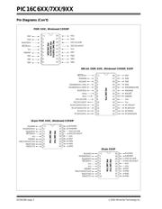
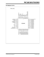
引脚图
产品图
页面导航:
引脚图在P1P2P3Hot
技术参数、封装参数在P1

导航目录
PIC16C74A-20/P数据手册
Page:
of 26 Go
若手册格式错乱,请下载阅览PDF原文件
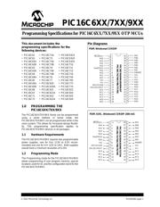
PIC16C6XX/7XX/9XX
DS30228K-page 4 2001 Microchip Technology Inc.
2.0 PROGRAM MODE ENTRY
2.1 User Program Memory Map
The user memory space extends from 0x0000 to
0x1FFF (8K). Table 2-1 shows actual implementation
of program memory in the PIC16C6XX/7XX/9XX
family.
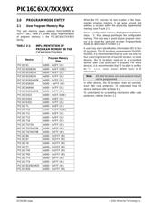
TABLE 2-1: IMPLEMENTATION OF
PROGRAM MEMORY IN THE
PIC16C6XX/7XX/9XX
When the PC reaches the last location of the imple-
mented program memory, it will wrap around and
address a location within the physically implemented
memory (see Figure 2-1).
Once in configuration memory, the highest bit of the PC
stays a ’1’, thus, always pointing to the configuration
memory. The only way to point to user program mem-
ory is to reset the part and re-enter Program/Verify
mode, as described in Section 2.2.
A user may store identification information (ID) in four
ID locations. The ID locations are mapped in [0x2000:
0x2003]. It is recommended that the user use only the
four Least Significant bits of each ID location. In some
devices, the ID locations read-out in a scrambled
fashion after code protection is enabled. For these
devices, it is recommended that ID location is written
as “11 1111 1bbb bbbb”, where 'bbbb' is ID
information.
In other devices, the ID locations read out normally,
even after code protection. To understand how the
devices behave, refer to Table 4-1.
To understand the scrambling mechanism after code
protection, refer to Section 3.1.
Device
Program Memory
Size
PIC16C61 0x000 – 0x3FF (1K)
PIC16C620/620A 0x000 – 0x1FF (0.5K)
PIC16C621/621A 0x000 – 0x3FF (1K)
PIC16C622/622A 0x000 – 0x7FF (2K)
PIC16C62/62A/62B 0x000 – 0x7FF (2K)
PIC16C63/63A 0x000 – 0xFFF (4K)
PIC16C64/64A 0x000 – 0x7FF (2K)
PIC16C65/65A/65B 0x000 – 0xFFF (4K)
PIC16CE623 0x000 – 0x1FF (0.5K)
PIC16CE624 0x000 – 0x3FF (1K)
PIC16CE625 0x000 – 0x7FF (2K)
PIC16C71 0x000 – 0x3FF (1K)
PIC16C710 0x000 – 0x1FF (0.5K)
PIC16C711 0x000 – 0x3FF (1K)
PIC16C712 0x000 – 0x3FF (1K)
PIC16C716 0x000 – 0x7FF (2K)
PIC16C72/72A 0x000 – 0x7FF (2K)
PIC16C73/73A/73B 0x000 – 0xFFF (4K)
PIC16C74/74A/74B 0x000 – 0xFFF (4K)
PIC16C66 0x000 – 0x1FFF (8K)
PIC16C67 0x000 – 0x1FFF (8K)
PIC16C76 0x000 – 0x1FFF (8K)
PIC16C77 0x000 – 0x1FFF (8K)
PIC16C745 0x000 – 0x1FFF (8K)
PIC16C765 0x000 – 0x1FFF (8K)
PIC16C773 0x000 – 0xFFF (4K)
PIC16C774 0x000 – 0xFFF (4K)
PIC16C923/924/925 0x000 – 0xFFF (4K)
PIC16C926 0x000 – 0x1FFF (8K)
Note: All other locations are reserved and should
not be programmed.
器件 Datasheet 文档搜索
AiEMA 数据库涵盖高达 72,405,303 个元件的数据手册,每天更新 5,000 多个 PDF 文件
