Datasheet 搜索 > 微控制器 > Microchip(微芯) > PIC16F690-I/P 数据手册 > PIC16F690-I/P 用户编程技术手册 4/38 页
 器件3D模型
¥ 23.939
PIC16F690-I/P 用户编程技术手册 - Microchip(微芯)
制造商:
Microchip(微芯)
分类:
微控制器
封装:
DIP-20
描述:
MICROCHIP PIC16F690-I/P 微控制器, 8位, 闪存, AEC-Q100, PIC16F, 20 MHz, 7 KB, 256 Byte, 20 引脚, DIP
Pictures:
3D模型
符号图
焊盘图
引脚图
产品图
页面导航:
引脚图在P1Hot
电气规格在P35
导航目录
PIC16F690-I/P数据手册
Page:
of 38 Go
若手册格式错乱,请下载阅览PDF原文件
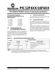
PIC12F6XX/16F6XX
DS41204H-page 4 2009 Microchip Technology Inc.
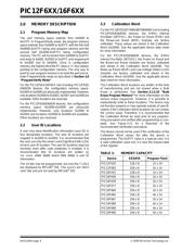
2.0 MEMORY DESCRIPTION
2.1 Program Memory Map
The user memory space extends from 0x0000 to
0x1FFF. In Program/Verify mode, the program memory
space extends from 0x0000 to 0x3FFF, with the first half
(0x0000-0x1FFF) being user program memory and the
second half (0x2000-0x3FFF) being configuration
memory. The PC will increment from 0x0000 to 0x1FFF
and wrap to 0x000, 0x2000 to 0x3FFF and wraparound
to 0x2000 (not to 0x0000). Once in configuration
memory, the highest bit of the PC stays a ‘1’, thus always
pointing to the configuration memory. The only way to
point to user program memory is to reset the part and re-
enter Program/Verify mode as described in Section 3.0
“Program/Verify Mode”.
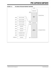
For the PIC12F6XX/16F6XX (not including PIC12F635/
636/639) devices, the configuration memory space,
0x2000 to 0x2008 are physically implemented. However,
only locations 0x2000 to 0x2003, 0x2007 and 0x2008 are
available. Other locations are reserved.
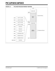
For the PIC12F635/636/639 devices, the configuration
memory space (0x2000-0x2009) are physically
implemented. However, only locations 0x2000 to
0x2003 and locations 0x2006 to 0x2009 are available.
Other locations are reserved.
2.2 User ID Locations
A user may store identification information (user ID) in
four designated locations. The user ID locations are
mapped in 0x2000 to 0x2003. It is recommended that
the user use only the seven Least Significant bits (LSb)
of each user ID location. The user ID locations read out
normally, even after code protection is enabled. It is
recommended that ID locations are written as
‘xx xxxx xbbb bbbb’ where ‘bbb bbbb’ is user ID
information.
The 14 bits may be programmed, but only the 7 LSb’s
are displayed by MPLAB
®
IDE. The xxxx’s are “don’t
care” bits and are not read by MPLAB
®
IDE.
2.3 Calibration Word
For the PIC16F631/677/685/687/689/690 (not including
PIC12F635/636/639) devices, the 8 MHz Internal
Oscillator (INTOSC), the Power-on Reset (POR) and
the Brown-out Reset (BOR) modules are factory
calibrated. These values are stored in the Calibration
Word (0x2008). See the applicable device data sheet
for more information.
For the PIC12F635/636/639 devices, the 8 MHz
Internal Oscillator (INTOSC), the Power-on Reset and
the Brown-out Reset modules are factory calibrated
and stored in the Calibration Word (0x2008). The
Wake-up Reset (WUR) and Low-Voltage Detect (LVD)
modules are factory calibrated and stored in the
Calibration Word (0x2009). See the applicable device
data sheet for more information.
The Calibration Word locations are written at the time
of manufacturing and are not erased when a Bulk
Erase is performed. See Section 3.1.5.10 “Bulk
Erase Program Memory” for more information on the
various erase sequences. However, it is possible to
inadvertently write to these locations. The device may
not function properly or may operate outside of specifi-
cations if the Calibration Word locations do not contain
the correct value. Therefore, it is recommended that
the Calibration Words be read prior to any program-
ming procedure and verified after programming is com-
plete. See Figure 3-21 for a flowchart of the
recommended verification procedure.
The device should not be used if the verification of the
Calibration Word values fail after the device is
programmed. The 0x3FFF value is a special case, it is
a valid calibration value but, it is also the erased state
of the register.
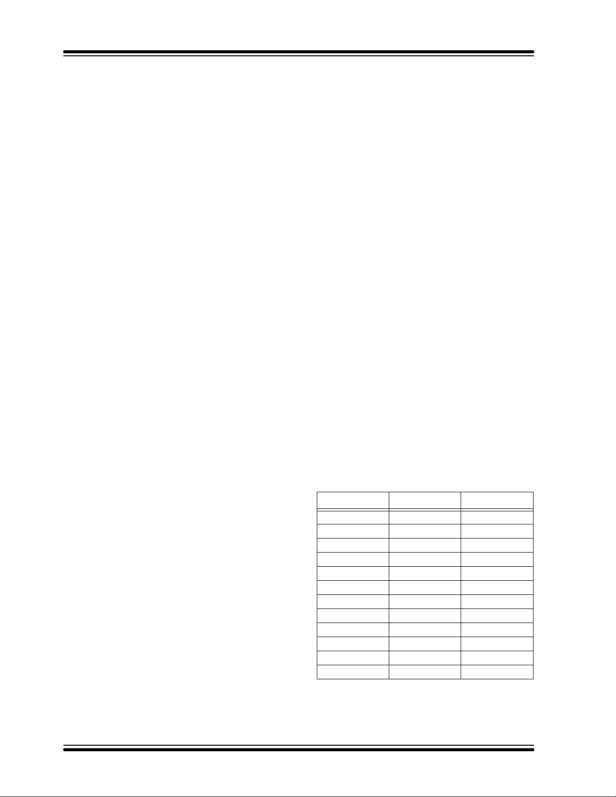
TABLE 1: MEMORY CAPACITY
Device EEDATA Program Flash
PIC12F635 128 x 8 1k x 14
PIC12F683 256 x 8 2k x 14
PIC16F631 128 x 8 1k x 14
PIC16F636 256 x 8 2k x 14
PIC16F639 256 x 8 2k x 14
PIC16F677 256 x 8 2k x 14
PIC16F684 256 x 8 2k x 14
PIC16F685 256 x 8 4k x 14
PIC16F687 256 x 8 2k x 14
PIC16F688 256 x 8 4k x 14
PIC16F689 256 x 8 4k x 14
PIC16F690 256 x 8 4k x 14
器件 Datasheet 文档搜索
AiEMA 数据库涵盖高达 72,405,303 个元件的数据手册,每天更新 5,000 多个 PDF 文件
