Datasheet 搜索 > 微控制器 > Microchip(微芯) > PIC16F877AT-I/PTG 数据手册 > PIC16F877AT-I/PTG 用户编程技术手册 1/4 页

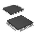
 器件3D模型
¥ 41.149
PIC16F877AT-I/PTG 用户编程技术手册 - Microchip(微芯)
制造商:
Microchip(微芯)
分类:
微控制器
封装:
TQFP-44
Pictures:
3D模型
符号图
焊盘图
引脚图
产品图
PIC16F877AT-I/PTG数据手册
Page:
of 4 Go
若手册格式错乱,请下载阅览PDF原文件

© 2005 Microchip Technology Inc. DS80240A-page 1
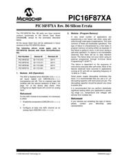
PIC16F87XA
The PIC16F87XA Rev. B6 parts you have received
conform functionally to the Device Data Sheet
(DS39582B), except for the anomalies described
below.
All the issues listed here will be addressed in future
revisions of the PIC16F87XA silicon.
The following silicon errata apply only to
PIC16F87XA devices with these Device/Revision
IDs:
1. Module: A/D (Operation)
The ADC is disabled when ADCON1<3:0> = 011x
(all inputs digital) and CMCON<2:0> = 111
(comparators are off). This is a special case that
conflicts with the second sentence of Note 1 on
page 131 of the device data sheet: “Pins
configured as digital inputs will convert an analog
input.”
Work around
For the ADC module to be enabled, it is necessary
to either:
1. Enable the comparators (CMCON<2:0> ≠ 111);
or
2. Configure at least one ADC channel as an
analog input (ADCON1<3:0> ≠ 011x).
2. Module: (Program Memory)
A very small number of applications are
experiencing a low failure rate when using self-
write through code types of applications. The most
common of these are bootloader operations. This
type of failure is characterized by a few bytes in
program memory not being written as expected. If
this failure is going to occur, it will occur during a
self-write operation. If a failure is not immediately
observed, then there will be no data retention
issues. The failure does not occur when using an
external programmer through In-Circuit Serial
Programming™ (ICSP™).
This failure is dependent on the sequence of
instructions executed after self-writes. Most of the
failures observed have occurred in applications
running at 5V and with an operating frequency of
12 MHz to 17 MHz.
Good power supply decoupling minimizes this
issue. It is recommended that you use a 0.1 μF
decoupling capacitor with each power pin pair. The
decoupling capacitor should be placed very close
to power pins.
It is recommended that you perform statistically
significant testing within your application’s operat-
ing range (i.e., temperature and voltage) with
devices from multiple lots.
Work around
If your devices are exhibiting this type of failure,
please contact your Microchip sales
representative.
Part Number Device ID Revision ID
PIC16F873A 00 1110 010 00111
PIC16F874A 00 1110 011 00111
PIC16F876A 00 1110 000 00111
PIC16F877A 00 1110 001 00111
PIC16F87XA Rev. B6 Silicon Errata
器件 Datasheet 文档搜索
AiEMA 数据库涵盖高达 72,405,303 个元件的数据手册,每天更新 5,000 多个 PDF 文件


