Datasheet 搜索 > UART接口芯片 > NXP(恩智浦) > SC16IS750IBS 数据手册 > SC16IS750IBS 用户编程技术手册 3/9 页

 器件3D模型
¥ 6.752
SC16IS750IBS 用户编程技术手册 - NXP(恩智浦)
制造商:
NXP(恩智浦)
分类:
UART接口芯片
封装:
HVQFN-24
描述:
UART 接口集成电路 I2C/SPI-UARTBRIDGE W/IRDA AND GPIO
Pictures:
3D模型
符号图
焊盘图
引脚图
产品图
页面导航:
应用领域在P8
导航目录
SC16IS750IBS数据手册
Page:
of 9 Go
若手册格式错乱,请下载阅览PDF原文件

AN10462_1 © Koninklijke Philips Electronics N.V. 2006. All rights reserved.
Application note Rev. 01 — 1 June 2006 3 of 9
Philips Semiconductors
AN10462
SPI programming for Philips Bridge ICs
1. Introduction
The Philips Bridge ICs are a new generation of interface solutions for managing
high-speed serial data communication among various bus interfaces such as SPI,
I
2
C-bus, and UARTs including RS-232 and RS-485. The Bridge IC is commonly used to
overcome the limitation of the host bus interface to peripherals and provides an easy
method to interface with existing different serial bus interfaces.
The description of the hardware connection and firmware programming are described in
the next paragraphs for users to quickly understand the implementation of Philips
P89LPC935 microcontroller with SPI-bus interface to Philips Bridge IC serial interface for
RS-232 point-point communication, RS-485 multi-drop application, IrDA wireless links,
and GPIO interface. The source code in C language is provided to show how to write a
simple communication program between the microcontroller and the Bridge IC serial
interface. The goal is to help users to design the Bridge IC in their application and also
shorten their product development cycle.
2. Hardware connection
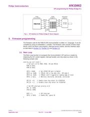
The block diagram depicted in Figure 1 shows the circuit connection of a Philips Bridge IC
such as SC16IS750 interfacing with Philips P89LPC935 microcontroller through the
SPI-bus. The Bridge IC offers simple, flexible, and minimal connection to the
microcontroller. The Bridge IC allows the microcontroller to easily control with few wires
connection through SPI-bus, which is a widely-used serial bus interface.
When the I2C/SPI
pin is at logic 0, the SPI-bus interface is selected and the Bridge IC can
interface to the microcontroller with a 4-wire connection. The signals on the 4 wires are
MISO (Master Input Slave Output), MOSI (Master Output Slave Input), CS
(active LOW
Chip Select), and SPICLK (SPI Clock).
The SPI-bus is a 4-wire full-duplex synchronous serial data link. Devices connected to the
SPI-bus are classified as master or slave devices. The master device initiates the data
transfer on the SPI-bus and also controls the slave devices with the chip select pins. The
slave devices are active only when selected. The interconnected devices share the same
V
CC
and GND.
After the microcontroller and Bridge IC are wired properly and their connection is
established, the microcontroller can send data to, and receive data from, UART devices
via the Bridge IC. The Bridge IC receives the SPI data from the microcontroller then sends
the data to the following devices: serial devices via RS-232 or RS-485 such as a modem,
wireless devices via IrDA such as a remote control, and general-purpose input/output
devices such as an LED and keypad. When the Bridge IC receives the data from the
devices, it will notify the microcontroller by generating an interrupt (IRQ
) output signal,
then the microcontroller can access the data from the Bridge IC via the SPI-bus interface.
器件 Datasheet 文档搜索
AiEMA 数据库涵盖高达 72,405,303 个元件的数据手册,每天更新 5,000 多个 PDF 文件


