Datasheet 搜索 > UART接口芯片 > NXP(恩智浦) > SC16IS750IBS,151 数据手册 > SC16IS750IBS,151 用户编程技术手册 4/9 页
 器件3D模型
¥ 8.621
SC16IS750IBS,151 用户编程技术手册 - NXP(恩智浦)
制造商:
NXP(恩智浦)
分类:
UART接口芯片
封装:
QFN-24
描述:
NXP SC16IS750IBS,151 芯片, 异步收发器, 单路, 64位FIFO, 5MBPS 3.6V, QFN-24
Pictures:
3D模型
符号图
焊盘图
引脚图
产品图
页面导航:
应用领域在P8

导航目录
SC16IS750IBS,151数据手册
Page:
of 9 Go
若手册格式错乱,请下载阅览PDF原文件
AN10462_1 © Koninklijke Philips Electronics N.V. 2006. All rights reserved.
Application note Rev. 01 — 1 June 2006 4 of 9
Philips Semiconductors
AN10462
SPI programming for Philips Bridge ICs
3. Firmware programming
The firmware code for the P89LPC935 microcontroller is written in C language. It can be
compiled by using an embedded C compiler. The firmware code consists of three major
blocks, which are Main Loop program, Interrupt service routine, and Bus interface layer,
as described in Section 3.1
, Section 3.2 and Section 3.3.
3.1 Main Loop
The Main Loop function is to program the microcontroller’s SPI port as a master by
initializing the SPI control register, interrupt handler, and chip select as shown in the
following sample code:
void mcu_spi_init (void) {
// Set port 2.0 for MOSI, MISO, /SS and SPICLK
P2M1 &= 0x42;
P2M2 &= 0x42;
SPCTL = 0x90; // Set LPC935 SPI port to Master
SPCTL &= ~0x08; // CPOL=0; SCK is low when idle – SPI mode 0
SPCTL &= ~0x04; // CPHA=0; shift triggered on leading edge of clock
SPCTL |= 0x11; // 00=clk/4, 01=clk/16, 10=clk/64, 11=clk/128
SPI_SS = 0; // Enable slave chip select for SC16IS7x0
SPI_SS = 1; // Disable slave chip select for SC16IS7x0
// Set SPI interrupt priority to 0
IP1 &= ~0x08;
IP1H &= ~0x08;
ESPI = 1; // SPI Interrupt
SPCTL |= 0xC0; // Enable SPI, ignore SS
}
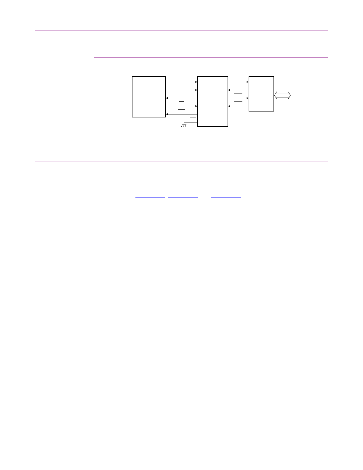
Fig 1. SPI interface to Philips Bridge IC block diagram
SC16IS740
SC16IS750
SC16IS760
SC16IS752
SC16IS762
002aac364
transceivers
(optional)
TxD
RxD
RTS
CTS
Philips
microcontroller
P89LPC935
Philips
Bridge ICs
RS-232
RS-485
SPICLK
MOSI
MISO
CS
IRQ
I2C/SPI
器件 Datasheet 文档搜索
AiEMA 数据库涵盖高达 72,405,303 个元件的数据手册,每天更新 5,000 多个 PDF 文件
