Datasheet 搜索 > CAN芯片 > Microchip(微芯) > MCP2515T-I/ST 数据手册 > MCP2515T-I/ST 开发手册 3/6 页
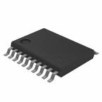
 器件3D模型
¥ 5.321
MCP2515T-I/ST 开发手册 - Microchip(微芯)
制造商:
Microchip(微芯)
分类:
CAN芯片
封装:
TSSOP-20
描述:
MICROCHIP MCP2515T-I/ST. 芯片, CAN总线控制器, 1MBPS, 4/3, 5.5V, TSSOP-20
Pictures:
3D模型
符号图
焊盘图
引脚图
产品图
页面导航:
功能描述在P2
导航目录
MCP2515T-I/ST数据手册
Page:
of 6 Go
若手册格式错乱,请下载阅览PDF原文件

2003 Microchip Technology Inc. DS00872A-page 3
AN872
F
OSC
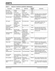
The maximum frequency of operation for the MCP2510
is 25 MHz (16 MHz for low voltage), whereas the
maximum for the MCP2515 is 40 MHz (25 MHz for low
voltage).
There is no impact when upgrading to the MCP2515.
SPI Clock
The maximum SPI frequencies for the MCP2510:
•5MHz for V
DD > 4.5V
• 4 MHz for E-temp V
DD
> 4.5V
• 2.5 MHz for V
DD = 3.0 to 4.5V
The maximum SPI clock frequency for the MCP2515 is
10 MHz across all voltages and temperatures.
There is no impact when upgrading to the MCP2515.
Operating Voltage
The MCP2510 operates from 3.0V to 5.5V, while the
MCP2515 operates from 2.7V to 5.5V.
There is no impact when upgrading to the MCP2515.
Data Byte Filtering
When receiving standard data frames (11-bit identifier),
the MCP2515 automatically applies 16 bits of the
masks and filters normally associated with extended
identifiers to the first 16-bits of the data field (data bytes
0 and 1). The MCP2510 does not have this feature.
The difference between the MCP2510 and MCP2515 is
the POR default state of the extended mask registers
(RXMnEID8 and RXMnEID0). The MCP2510 POR
defaults are undefined and can power-up in any state.
The MCP2515 POR defaults equals zero for these
registers to effectively turn the masks off (i.e., do not
apply filters to the data bytes).
If the original application with the MCP2510 does not
use extended frames and does not initialize the
extended mask registers (or initializes them to zero),
the MCP2515 can be placed in the socket with no MCU
firmware modifications.
One-shot Mode
The MCP2515 implements a feature to ensure that a
transmit message is attempted only one time. With
One-shot mode enabled, a message will attempt
transmission only one time, regardless of arbitration
loss or error frame.
This enable bit is located in CANCTRL.bit3. This
location is unused and reads zero in the MCP2510.
If the original application does not attempt to initialize
this location to a logic one (which it should not because
the bit is unimplemented in the MCP2510), then using
the MCP2515 will have no effect on the operation.
Start-of-Frame (SOF) Signal
The MCP2515 implements a feature that, if enabled,
will generate a pulse on the CLKOUT/SOF pin if the
RXCAN pin detects the beginning of a CAN message.
The SOF bit is located in CNF3.bit7. This location is
unused and reads zero on the MCP2510.
If the original application does not attempt to initialize
this location to a logic one (which it should not because
the bit is unimplemented in the MCP2510), then using
the MCP2515 will have no effect on the operation.
Three New SPI Instructions
See the "Enhancements" section and the MCP2515
data sheet for details.
Number of Clocks on CLKOUT Pin Before
Entering Sleep Mode
After requesting Sleep mode, the MCP2510 generates
16 additional clocks on CLKOUT (if enabled) before
entering Sleep mode. The MCP2515 generates 17
additional clocks.
Setting ABAT Bit to Abort Messages
The MCP2510 will only set the abort flag
(TXBnCTRL.ABTF) when requesting an abort via
CANCTRL.ABAT if the associated message was
pending (TXREQ = 1) and then successfully aborted.
The MCP2515 sets the abort flag (TXBnCTRL.ABTF)
regardless of the associated TXREQ value. However,
the MCP2515 will abort the message if it is pending.
Using the MCP2515 in an application designed for the
MCP2510 will have very little impact because the
MCP2515 is better at aborting messages (see
“Aborting Pending Messages”).
Aborting Pending Messages
The MCP2510 can only abort messages that are
pending and have not attempted to transmit. This
includes messages that go back to the pending state
due to loss of arbitration, error frames, etc. This is
because the TXBnCTRL.TXREQ bit gets locked out
and cannot be cleared if the associated buffer attempts
to transmit. The only exception is if another transmit
buffer becomes pending and has a higher buffer
priority.
The MCP2515 can abort any pending message.
Setting CANCTRL.ABAT will clear the associated
TXREQ bit. If the transmitting buffer is interrupted, it
checks the TXREQ bit before attempting to transmit
again, and if cleared, will not attempt to transmit.
The enhanced aborting capabilities of the MCP2515
should have minimal affect when replacing the
MCP2510.
器件 Datasheet 文档搜索
AiEMA 数据库涵盖高达 72,405,303 个元件的数据手册,每天更新 5,000 多个 PDF 文件

