Datasheet 搜索 > CAN芯片 > Microchip(微芯) > MCP2515T-I/ST 数据手册 > MCP2515T-I/ST 开发手册 4/6 页
 器件3D模型
¥ 5.321
MCP2515T-I/ST 开发手册 - Microchip(微芯)
制造商:
Microchip(微芯)
分类:
CAN芯片
封装:
TSSOP-20
描述:
MICROCHIP MCP2515T-I/ST. 芯片, CAN总线控制器, 1MBPS, 4/3, 5.5V, TSSOP-20
Pictures:
3D模型
符号图
焊盘图
引脚图
产品图
页面导航:
功能描述在P2


导航目录
MCP2515T-I/ST数据手册
Page:
of 6 Go
若手册格式错乱,请下载阅览PDF原文件

AN872
DS00872A-page 4 2003 Microchip Technology Inc.
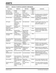
Error Warning Flags (EWARN and
RXWARN)
The EWARN and RXWARN flag bits, located in EFLG,
will clear if the MCP2510 transitions from error-warning
to error-passive.
For the MCP2515, the EWARN and RXWARN bits stay
set if the device transitions to error-passive.
The impact when upgrading to the MCP2515 should be
minimal because an interrupt is generated (if enabled)
whenever either condition is true. If polling for the error
condition, it is possible (though not probable) that the
firmware could mistake an error-passive state as an
error-warning state.
Sleep Mode
To enter Sleep mode with either device, the
CANCTRL.REQOP bits equal b’001’. Once in Sleep
mode, the REQOP bits remain unchanged in the
MCP2510. However, the MCP2515 REQOP bits will
change to b’011’ to request Listen-only mode as soon
as the device wakes up from Sleep mode. Note that the
CANSTAT.OPMOD bits still reflect the current mode,
which is Sleep in this case.
The MCP2515 should have minimal affect on the
application when replacing the MCP2510 because the
application should read CANSTAT.OPMOD when
checking the operation mode. The REQOP bits are
only used for requesting modes of operation, not
verifying modes.
Modifying REQOP Bits While In Sleep
Mode
The CANCTRL.REQOP bits are writable on the
MCP2510 while in Sleep mode. The REQOP bits are
read-only on the MCP2515 while in Sleep mode.
The impact of upgrading to the MCP2515 should be
minimal because the modes cannot be changed on
either device while in Sleep mode.
Requesting Sleep Mode
When requesting Sleep mode, the MCP2510 will
immediately enter Sleep mode, regardless of bus
activity. The MCP2515 will wait until a bus idle condition
before entering Sleep mode.
There should be no negative impact when upgrading to
the MCP2515.
Standby Current
The maximum standby (Sleep mode) current on the
MCP2510 is 5 µA across all temperatures. The
maximum standby current on the MCP2515 is 5 µA for
temperatures up to 85°C and 8 µA for temperatures
from 85°C to 125°C.
The impact of an upgrade should be minimal because
the typical currents between the two devices are
extremely similar.
SPI Bit Modify Command
On the MCP2510, the Bit Modify command can only be
used on specific registers, as identified in the device’s
data sheet. While this is essentially true for the
MCP2515 as well, if a Bit Modify command is used on
a register whose bits cannot be modified, the mask
byte is ignored and effectively becomes FFh. The
command is basically a byte write command with eight
extra clocks (mask byte).
There should be no impact when upgrading to the
MCP2515 because the MCP2510 application would
not attempt to Bit Modify a register whose bits cannot
be modified.
Error Counters While In Listen-only mode
The MCP2510 error counters are reset and deactivated
while in Listen Only mode. The MCP2515 error
counters are not reset, but are still deactivated, while in
Listen-only mode.
The impact when upgrading to the MCP2515 should be
minimal.
Reading The Mask And Filters While Not
In Configruation Mode
The MCP2510 can read the masks and filters in all
modes, while the MCP2515 can only read the masks
and filters while in Configuration mode. The registers
will read 00h while not in Configuration mode. This
serves as a positive lockout for the other modes.
The impact when upgrading should be minimal
because the masks and filters on either device can be
modified only when in Configuration mode. The masks
and filters most likely will not need to be read after
leaving Configuration mode.
SUMMARY
While the MCP2515 was designed to be pin and
functionally compatible with the MCP2510, there are
some differences between the devices due to
enhancements, errata fixes, design differences,
process differences, etc. that the MCP2515
incorporates.
This application note helps the design engineer
determine the impact of upgrading their system or
module from an MCP2510 to a MCP2515. In most
cases, the impact should be nonexistent (or invisible)
because the functional differences are a superset of
the MCP2510 functinality.
器件 Datasheet 文档搜索
AiEMA 数据库涵盖高达 72,405,303 个元件的数据手册,每天更新 5,000 多个 PDF 文件
