Datasheet 搜索 > 运算放大器 > Microchip(微芯) > MCP604T-I/ST 数据手册 > MCP604T-I/ST 开发手册 6/10 页
 器件3D模型
¥ 7.873
MCP604T-I/ST 开发手册 - Microchip(微芯)
制造商:
Microchip(微芯)
分类:
运算放大器
封装:
TSSOP-14
描述:
MCP604系列 6V 2.8MHz 单电源 CMOS 运算放大器-TSSOP-14
Pictures:
3D模型
符号图
焊盘图
引脚图
产品图
页面导航:
技术参数、封装参数在P8
应用领域在P8
导航目录
MCP604T-I/ST数据手册
Page:
of 10 Go
若手册格式错乱,请下载阅览PDF原文件
AN682
DS00682C-page 6 2000 Microchip Technology Inc.
With this configuration, the voltage of V
REF
is reduced
via the first resistor, R
1
, by the voltage VR1. The voltage
applied to the non-inverting input of the top op amp is
V
REF
− V
R1
. This voltage is gained to the amplifier’s out-
put by two to equal 2(V
REF
− V
R1
). Meanwhile, the out-
put for the bottom op amp is presented with the voltage
V
REF
− 2V
R1
. Subtracting the voltage at the output of the
top amplifier from the non-inverting input of the bottom
amplifier gives 2(V
REF
− V
R1
) − (V
REF
− 2V
R1
) which
equals V
REF
.
The transfer function of the circuit is:
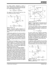
Filters
Bandpass and low pass filters are very useful in elimi-
nating unwanted signals prior to the input of an A/D
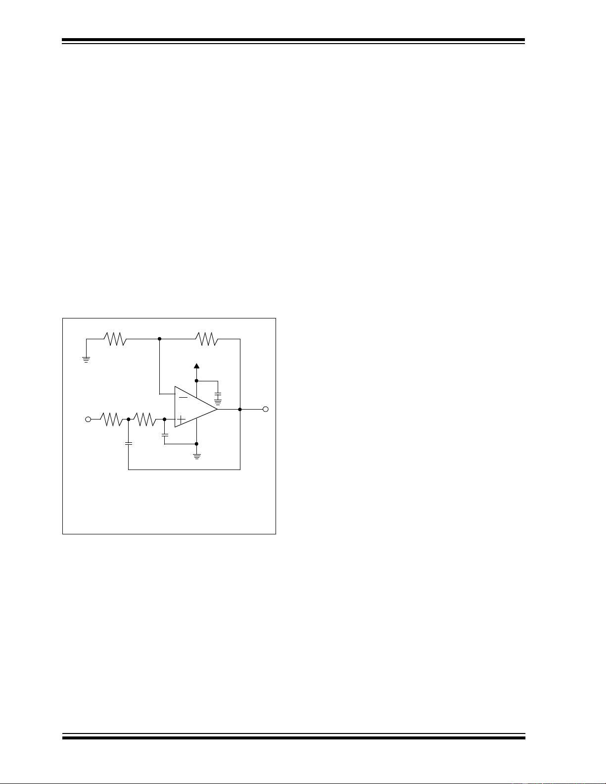
converter. The low pass filter shown in Figure 12 has
two poles that can be configured for a Butterworth filter
response. Butterworth filters have a flat magnitude
response in the pass-band with good all-around perfor-
mance.
Figure 12: Low pass, 2-pole, active filters are easily
designed with one operational amplifier. The resistors
and capacitors can be adjusted to implement other
filter types, such as Bessel and Chebyshev.
On the down side, there is some overshoot and ringing
with a step response through this filter. This may or
may not be an issue, depending on the application cir-
cuit requirements. The gain of this filter is adjustable
with R
3
and R
4
.
Notice the similarities in this gain equation and the
non-inverting amplifier shown in Figure 3.
This type of filter is also referred to as an anti-aliasing
filter, which is used to eliminate circuit noise in the fre-
quency band above half of nyquist of the sampling sys-
tem. In this manner, these high frequency noises, that
would typically alias back into the signal path, are
removed.
The DC gain of the circuit in Figure 12 is:
The bandpass filter shown in Figure 13 is configured
with a zero and two poles to accommodate speech
applications. The single zero high pass filter portion of
this circuit is constructed with C
1
and R
1
in parallel with
R
2
. Notice that R
1
and R
2
also creates a supply splitter
voltage at the non-inverting inputs of both of the ampli-
fiers. This insures that both operational amplifiers oper-
ate in their linear region. The second amplifier, U
2
, in
conjunction with the components R
3
, R
4
, C
3
, and C
4
set a two pole corner frequency. This filter eliminates
high frequency noise that may be aliased back into the
signal path.
The signal gain of this circuit is:
For more details about low pass filters refer to AN699
“Anti-aliasing Analog Filters for Data Acquisitions
Systems”.
I
OUT
V
REF
R
L
-------------=
V
OUT
Second Order: 10kHz, Low Pass Sallen Key Filter
V
IN
R
3
R
4
R
1
R
2
C
2
C
1
*
MCP601
100k
Ω
909kΩ
54.9kΩ
97.6kΩ
100pF
470pF
*Bypass Capacitor, 1µF
V
OUT
V
IN
------------- 1
R
4
R
3
------+
=
V
DD
V
OUT
V
IN
------------- 1
R
4
R
3
------+
=
V
OUT
V
IN
R
3
R
4
------
R
2
R
1
R
2
+
-------------------
=
器件 Datasheet 文档搜索
AiEMA 数据库涵盖高达 72,405,303 个元件的数据手册,每天更新 5,000 多个 PDF 文件
