Datasheet 搜索 > 微控制器 > Microchip(微芯) > PIC16F684T-I/ST 数据手册 > PIC16F684T-I/ST 开发手册 3/24 页
 器件3D模型
¥ 18.75
PIC16F684T-I/ST 开发手册 - Microchip(微芯)
制造商:
Microchip(微芯)
分类:
微控制器
封装:
TSSOP-14
描述:
MICROCHIP PIC16F684T-I/ST 微控制器, 8位, 闪存, AEC-Q100, PIC16F6xxx, 20 MHz, 3.5 KB, 128 Byte, 14 引脚, TSSOP
Pictures:
3D模型
符号图
焊盘图
引脚图
产品图
页面导航:
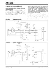
原理图在P6P8
应用领域在P11P13
导航目录
PIC16F684T-I/ST数据手册
Page:
of 24 Go
若手册格式错乱,请下载阅览PDF原文件

2010 Microchip Technology Inc. DS01310A-page 3
AN1310
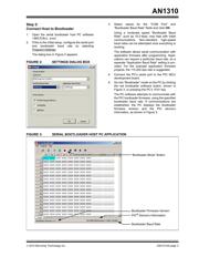
Step 2:
Connect Host to Bootloader
1. Open the serial bootloader host PC software
(AN1310ui.exe).
2. If this is the initial setup, configure the serial port
and bootloader baud rate by selecting
Program>Settings
.
The dialog box in Figure 2 appears.
FIGURE 2: SETTINGS DIALOG BOX
3. Select values for the “COM Port” and
“Bootloader Baud Rate” fields and click OK.
Using a moderate speed “Bootloader Baud
Rate”, such as 19.2 kbps, may help with initial
communications. Non-standard, high-speed
baud rates can be attempted once everything is
working.
The software allows serial communication with
application firmware after programming. Appli-
cations can require a particular baud rate, so a
separate “Application Baud Rate” setting is pro-
vided. For the example application firmware
projects, the 115,200 bps rate is suggested.
4. Connect the PC's serial port to the PIC MCU
development board.
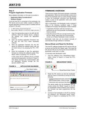
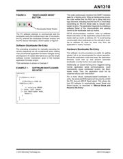
5. Go into “Bootloader” mode on the PC by clicking
the red bootloader software button, shown in
Figure 3, or pressing the PC’s <F4> key.
The PC software attempts to communicate with
the PIC bootloader firmware, using the specified
bootloader baud rate. If communications are
established, the PC displays the bootloader
firmware revision and the PIC device’s
information, as shown in Figure 3.
FIGURE 3: SERIAL BOOTLOADER HOST PC APPLICATION
Bootloader Firmware Version
PIC
®
Device’s Information
Bootloader Baud Rate
“Bootloader Mode” Button
器件 Datasheet 文档搜索
AiEMA 数据库涵盖高达 72,405,303 个元件的数据手册,每天更新 5,000 多个 PDF 文件
