Datasheet 搜索 > 接口芯片 > Maxim Integrated(美信) > MAX4582CSE 数据手册 > MAX4582CSE 数据手册 8/17 页
 器件3D模型
¥ 7.189
MAX4582CSE 数据手册 - Maxim Integrated(美信)
制造商:
Maxim Integrated(美信)
分类:
接口芯片
封装:
SOIC-16
描述:
低电压, CMOS模拟多路复用器/开关 Low-Voltage, CMOS Analog Multiplexers/Switches
Pictures:
3D模型
符号图
焊盘图
引脚图
产品图
页面导航:
导航目录
MAX4582CSE数据手册
Page:
of 17 Go
若手册格式错乱,请下载阅览PDF原文件
MAX4581/MAX4582/MAX4583
Low-Voltage, CMOS Analog
Multiplexers/Switches
8 _______________________________________________________________________________________
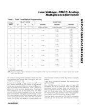
__________Applications Information
Power-Supply Considerations
Overview
The MAX4581/MAX4582/MAX4583 construction is typi-
cal of most CMOS analog switches. They have three
supply pins: V
CC
, V
EE
, and GND. V
CC
and V
EE
are used
to drive the internal CMOS switches and set the limits of
the analog voltage on any switch. Reverse ESD-
protection diodes are internally connected between
each analog-signal pin and both V
CC
and V
EE
. If any
analog signal exceeds V
CC
or V
EE
, one of these diodes
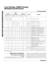
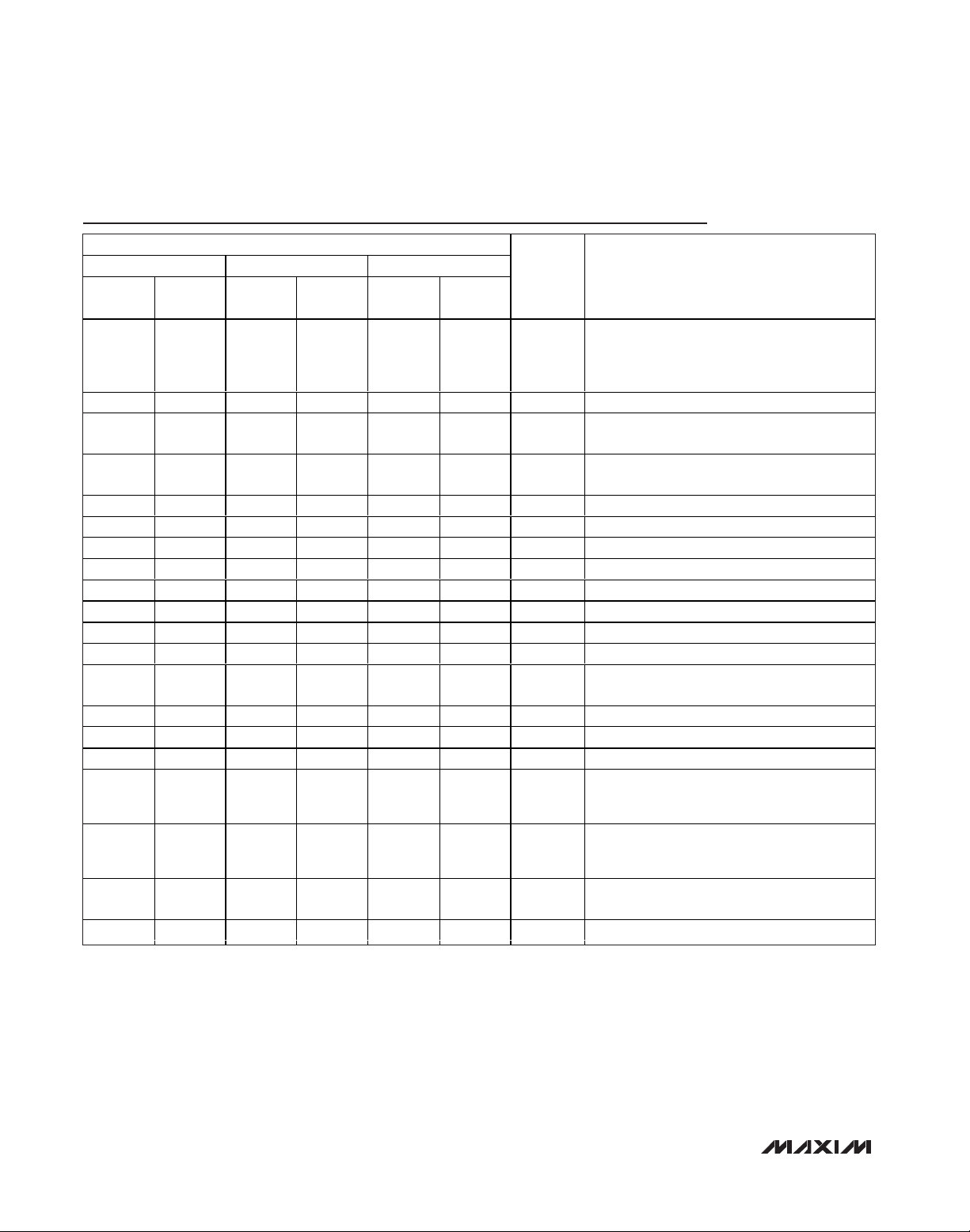
Pin Description
Note: Input and output pins are identical and interchangeable. Any may be considered an input or output; signals pass equally well
in both directions.
PIN
MAX4581 MAX4582 MAX4583
PDIP, SO,
TSSOP
TQFN-EP
PDIP, SO,
TSSOP
TQFN-EP
PDIP, SO,
TSSOP
TQFN-EP
NAME FUNCTION
13, 14,
15, 12,
1, 5, 2, 4
11, 12,
13, 10,
15, 3,
16, 2
— — — — X0–X7 Analog Switch Inputs 0–7
3 1 13 11 14 12 X Analog Switch “X” Output
——
12, 14,
15, 11
10, 12,
13, 9
——
X0, X1,
X2, X3
Analog Switch “X” Inputs 0–3
——
1, 5, 2,
4
15, 3,
16, 2
——
Y0, Y1,
Y2, Y3
Analog Switch “Y” Inputs 0–3
— — 3 1 15 13 Y Analog Switch “Y” Output
— — — — 13 11 X1 Analog Switch “X” Normally Open Input
— — — — 12 10 X0 Analog Switch “X” Normally Closed Input
— — — — 1 15 Y1 Analog Switch “Y” Normally Open Input
— — — — 2 16 Y0 Analog Switch “Y” Normally Open Input
— — — — 3 1 Z1 Analog Switch “Z” Normally Open Input
— — — — 5 3 Z0 Analog Switch “Z” Normally Open Input
— — — — 4 2 Z Analog Switch “Z” Output
16 14 16 14 16 14 V
CC
Positive Analog and Digital Supply-Voltage
Input
11 9 10 8 11 9 A Digital Address “A” Input
10 8 9 7 10 8 B Digital Address “B” Input
9 7 — — 9 7 C Digital Address “C” Input
868686GND
Ground. Connect to digital ground. (Analog
signals have no ground reference; they are
limited to V
CC
and V
EE
.)
757575V
EE
Negative Analog Supply-Voltage Input.
Connect to GND for
single-supply operation.
6 4 6 4 6 4 ENABLE
Digital Enable Input. Normally connected to
GND.
——————EPE xp osed P ad ( TQ FN onl y) . C onnect E P to V
C C
.
器件 Datasheet 文档搜索
AiEMA 数据库涵盖高达 72,405,303 个元件的数据手册,每天更新 5,000 多个 PDF 文件
