Datasheet 搜索 > ADI(亚德诺) > AD8045 数据手册 > AD8045 其他数据使用手册 1/8 页


¥ 0
AD8045 其他数据使用手册 - ADI(亚德诺)
制造商:
ADI(亚德诺)
描述:
3内华达州/ Hz的超低失真,高速运算放大器 3 nV/Hz Ultralow Distortion, High Speed Op Amp
Pictures:
3D模型
符号图
焊盘图
引脚图
产品图
页面导航:
应用领域在P8
导航目录
AD8045数据手册
Page:
of 8 Go
若手册格式错乱,请下载阅览PDF原文件
a
AN-417
APPLICATION NOTE
ONE TECHNOLOGY WAY
•
P.O. BOX 9106
•
NORWOOD, MASSACHUSETTS 02062-9106
•
617/329-4700
Movement towards lower power supply voltages is
driven by the demand that systems consume less and
less power coupled with the desire to reduce the num-
ber of power supply voltages in the system. Lowering
power supply voltages and reducing the number of sup-
plies has obvious advantages. One such advantage is to
lower system power consumption. This has the addi-
tional benefit of saving space. Lowering overall power
consumption has a residual benefit in that there may no
longer be a need for cooling fans in the system.
However, as the traditional system power supply
voltages of ±15 V and ±12 V give way to lower bipolar
supplies of ±5 V and single supplies of +5 V and +3.3 V, it
is necessary for circuit designers to understand that de-
signing in this new environment is not simply a matter
of finding components that are specified to operate at
lower voltages. Not all design principles used in the
past can be directly translated to a lower voltage
environment.
Reducing the power supply voltage to a typical op amp
has a number of effects. Obviously, the signal swings
both at the input and output are reduced. The required
headroom between signal and rail (typically 1 V to 2 V in
conventional amplifiers), which is of lesser importance
with power supplies of ±15 V, now drastically reduces
the usable signal range. While this reduction does not
normally increase noise levels in the system, signal-to-
noise ratios will be degraded. Because the designer can
no longer use techniques such as increasing power sup-
ply voltages and signal swings in order to “swamp”
noise levels, greater attention must be paid to noise
levels in the system.
Both bandwidth and slew rate decrease as power sup-
plies drop. However, it should be noted that smaller
signal swings need lower slew rates to maintain the
same bandwidth. In choosing an operational amplifier,
close study of the data sheet is essential. Data sheet
specifications that list slew rate and bandwidth under
different power supply conditions (e.g., ±5 V, +5 V and
+3 V), along with corresponding loading conditions, are
useful and necessary here.
Rail-to-rail amplifiers are seen as a solution to the
dilemma of decreasing power supply voltages. The term
rail-to-rail, while not exactly defined, refers to devices
whose inputs and/or outputs can swing close to both
rails. This definition does not put an exact value on
“close to both rails”, nor does it specify the loading con-
ditions under which rail-to-rail performance must be
maintained. Rail-to-rail op amps are a subset of single-
supply op amps which are devices that operate on a
single rail. The inputs and outputs of a single-supply op
amp may or may not be able to approach the rails. In
order to work successfully with rail-to-rail and single-
supply op amps, an basic understanding of some com-
monly used output stages is necessary.
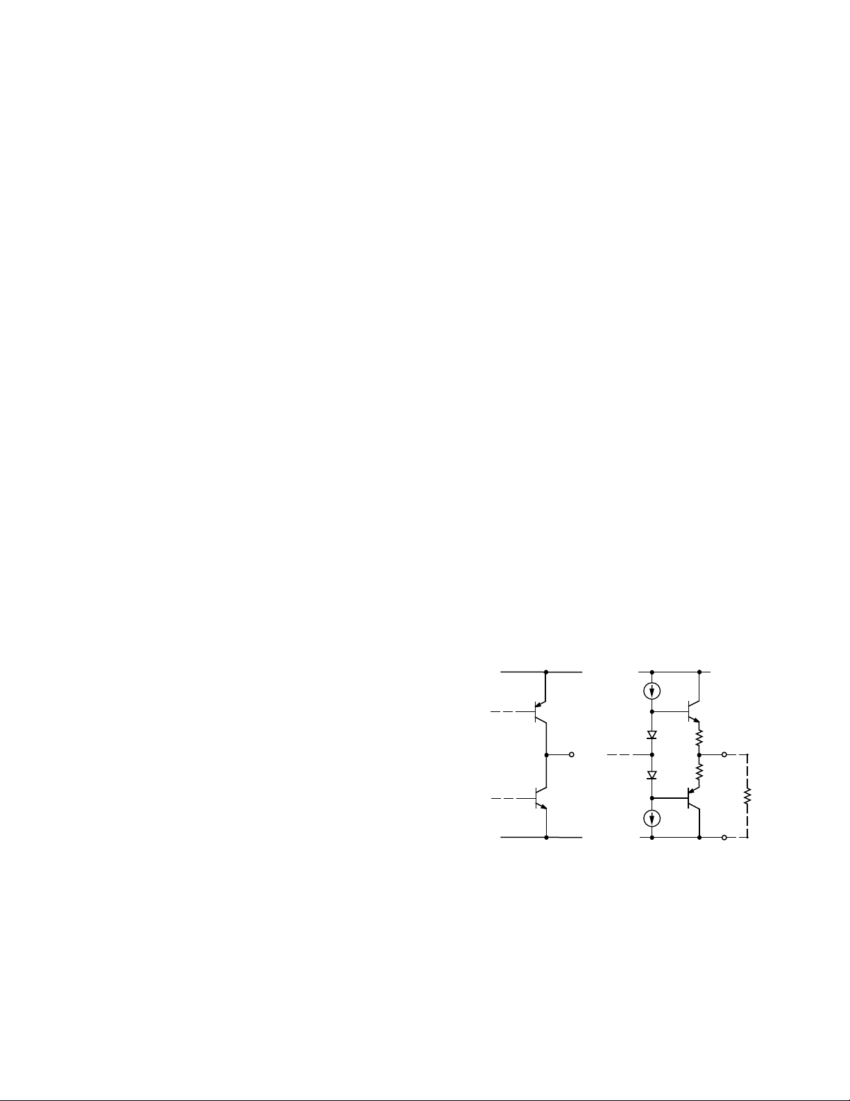
OUTPUT
+V
S
–V
S
COMMON EMITTER
OUTPUT
+V
S
–V
S
R
L
50Ω TO
500Ω
EMITTER FOLLOWER
Figure 1. Common Op Amp Output Stages
Figure 1 shows two typical high speed op amp output
stages. The emitter-follower stage is widely used in low
distortion op amps. Its output voltage swing is limited to
slightly greater than one diode drop from the rails. In
reality, the headroom is closer to 1 V. In order to main-
tain low distortion at high frequencies, even more
headroom may be required, reducing the available
Fast Rail-to-Rail Operational Amplifiers Ease Design Constraints in Low Voltage
High Speed Systems
by Eamon Nash
器件 Datasheet 文档搜索
AiEMA 数据库涵盖高达 72,405,303 个元件的数据手册,每天更新 5,000 多个 PDF 文件
