Datasheet 搜索 > EEPROM芯片 > ATMEL(爱特美尔) > AT24C128W-10SC-2.7 数据手册 > AT24C128W-10SC-2.7 其他数据使用手册 4/16 页

¥ 53.238
AT24C128W-10SC-2.7 其他数据使用手册 - ATMEL(爱特美尔)
制造商:
ATMEL(爱特美尔)
分类:
EEPROM芯片
封装:
SOEIAJ-8
Pictures:
3D模型
符号图
焊盘图
引脚图
产品图

AT24C128W-10SC-2.7数据手册
Page:
of 16 Go
若手册格式错乱,请下载阅览PDF原文件
AT24C128/256
4
Notes: 1. This parameter is characterized and is not 100% tested.
2. AC measurement conditions:
R
L
(connects to V
CC
): 1.3KΩ (2.7V, 5V), 10KΩ (1.8V)
Input pulse voltages: 0.3V
CC
to 0.7V
CC
Input rise and fall times: ≤50ns
Input and output timing reference voltages: 0.5V
CC
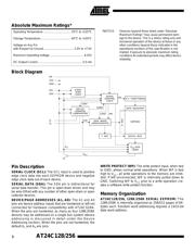
Device Operation
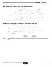
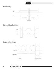
CLOCK and DATA TRANSITIONS: The SDA pin is nor-
mally pulled high with an external device. Data on the SDA
pin may change only during SCL low time periods (refer to
Data Validity timing diagram). Data changes during SCL
high periods will indicate a start or stop condition as defined
below.
START CONDITION: A high-to-low transition of SDA with
SCL high is a start condition which must precede any other
command (refer to Start and Stop Definition timing dia-
gram).
STOP CONDITION: A low-to-high transition of SDA with
SCL high is a stop condition. After a read sequence, the
stop command will place the EEPROM in a standby power
mode (refer to Start and Stop Definition timing diagram).
ACKNOWLEDGE: All addresses and data words are seri-
ally transmitted to and from the EEPROM in 8-bit words.
The EEPROM sends a zero during the ninth clock cycle to
acknowledge that it has received each word.
STANDBY MODE: The AT24C128/256 features a low
power standby mode which is enabled: a) upon power-up
and b) after the receipt of the STOP bit and the completion
of any internal operations.
MEMORY RESET: After an interruption in protocol, power
loss or system reset, any 2-wire part can be reset by follow-
ing these steps: (a) Clock up to 9 cycles, (b) look for SDA
high in each cycle while SCL is high and then (c) create a
start condition as SDA is high.
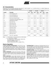
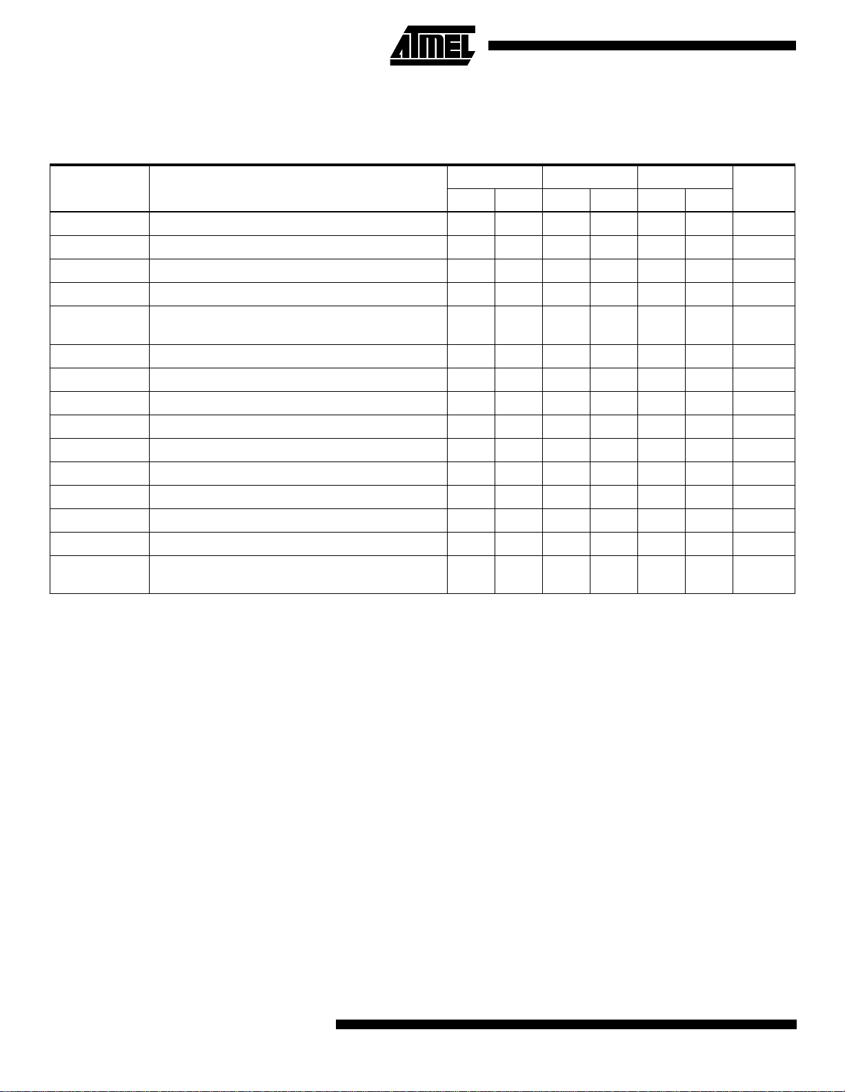
AC Characteristics
Applicable over recommended operating range from T
A
= -40°C to +85°C, V
CC
= +1.8V to +5.5V, CL = 100 pF (unless oth-
erwise noted). Test conditions are listed in Note 2.
Symbol Parameter
1.8-volt 2.7-volt 5.0-volt
UnitsMin Max Min Max Min Max
f
SCL
Clock Frequency, SCL 100 400 1000 kHz
t
LOW
Clock Pulse Width Low 4.7 1.3 0.6 µs
t
HIGH
Clock Pulse Width High 4.0 1.0 0.4 µs
t
AA
Clock Low to Data Out Valid 0.1 4.5 0.05 0.9 0.05 0.55 µs
t
BUF
Time the bus must be free before a new
transmission can start
(1)
4.7 1.3 0.5 µs
t
HD.STA
Start Hold Time 4.0 0.6 0.25 µs
t
SU.STA
Start Set-up Time 4.7 0.6 0.25 µs
t
HD.DAT
Data In Hold Time 0 0 0 µs
t
SU.DAT
Data In Set-up Time 200 100 100 ns
t
R
Inputs Rise Time
(1)
1.0 0.3 0.3 µs
t
F
Inputs Fall Time
(1)
300 300 100 ns
t
SU.STO
Stop Set-up Time 4.7 0.6 0.25 µs
t
DH
Data Out Hold Time 100 50 50 ns
t
WR
Write Cycle Time 20 10 10 ms
Endurance
(1)
5.0V, 25°C, Page Mode 100K 100K 100K
Write
Cycles
器件 Datasheet 文档搜索
AiEMA 数据库涵盖高达 72,405,303 个元件的数据手册,每天更新 5,000 多个 PDF 文件
