Datasheet 搜索 > 实时时钟芯片 > Maxim Integrated(美信) > DS1337S+C01 数据手册 > DS1337S+C01 其他数据使用手册 1/7 页

 器件3D模型
¥ 0
DS1337S+C01 其他数据使用手册 - Maxim Integrated(美信)
制造商:
Maxim Integrated(美信)
分类:
实时时钟芯片
封装:
SOIC-8
Pictures:
3D模型
符号图
焊盘图
引脚图
产品图


DS1337S+C01数据手册
Page:
of 7 Go
若手册格式错乱,请下载阅览PDF原文件

Maxim > Design Support > Technical Documents > Tutorials > Real-Time Clocks > APP 5791
Keywords: real-time clock (RTC), counter chain
TUTORIAL 5791
Tips for Writing Bulletproof Real-Time Clock Control Code
Mar 28, 2014
Abstract:
With the use
of proper device initialization and code sequencing, accurate timekeeping and clock alarm operations
become a more manageable task.
Introduction
When we read a clock, as we have all done since childhood, our eyes 'take a snapshot' of the present displayed values.
Someone has already gone through the effort to reorient that display for your readability. When the microprocessor needs
to access the real-time clock, the 'snapshot' of the latest register values must be reoriented into a sequence of time counts
that we are more familiar with.
With the use of proper device initialization and code sequencing, accurate timekeeping and clock alarm operations become
a more manageable task.
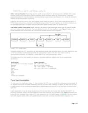
Device Initialization
Upon the first power application to a new clock component, the sequence of required I/O instructions may vary, based upon
that specific component. Refer to the device specification for register structuring. As a general guideline, and assuming
power is stable and the I/O port is operational, it is recommended to:
1. Enable writing to the chip (if a software write-protection option exists)
2. Enable the 32kHz RTC oscillator (if not auto-started)
3. Define the hardware interrupt output configuration(s) (as applicable)
4. Load initial counter values
Enable Writing to the RTC: This unique function was added to some component designs (for example, the DS1305) to
prevent inadvertent clock changes. Refer to the product specification for the write-protect (WP) bit explanation.
Enable RTC Oscillator: On some legacy designs (such as DS12887, DS1307), the RTC oscillator does not auto-start at
first power-up. This operational feature was intended to prevent battery consumption during transit/storage, and must be
enabled through I/O. Designs with an active-low
EOSC bit
in the Control register include a built-in oscillator auto-start
function, executed upon the first power application. In some other designs like DS1685, it may also be necessary to identify
the crystal load capacitance setting for proper oscillator operation.
Check 'OSF': Some RTC components contain an oscillator stop flag (OSF), allowing the user to monitor oscillator operation
via periodic I/O. Upon initial power application, OSF will be set. After enabling the oscillator, clear OSF, and then
periodically verify that the OSF bit remains Logic 0.
OSF may become Logic 1 based upon any of these conditions:
1. Initial application of power
2. Voltages on VCC and VBAT are insufficient to maintain oscillator operation
3. active-low
EOSC bit
was set to 1, stopping the oscillator
Page 1 of 7
器件 Datasheet 文档搜索
AiEMA 数据库涵盖高达 72,405,303 个元件的数据手册,每天更新 5,000 多个 PDF 文件
