Datasheet 搜索 > 实时时钟芯片 > Maxim Integrated(美信) > DS1337S+C01 数据手册 > DS1337S+C01 其他数据使用手册 2/7 页

 器件3D模型
¥ 0
DS1337S+C01 其他数据使用手册 - Maxim Integrated(美信)
制造商:
Maxim Integrated(美信)
分类:
实时时钟芯片
封装:
SOIC-8
Pictures:
3D模型
符号图
焊盘图
引脚图
产品图

DS1337S+C01数据手册
Page:
of 7 Go
若手册格式错乱,请下载阅览PDF原文件
4. External influences upon the crystal (leakage, coupling, etc.)
Define Interrupt Output(s): Depending upon the specific component and the desired application, definition of the output
functions should now be executed to prevent unintended signals from being sent to the microprocessor. Component
programming options for real-time alarm(s), watchdog interrupt, square-wave output frequency, etc., should be selected to
establish the desired pin/signal conditioning.
In devices with real-time alarms, every alarm register should initially be written to 00h (if binary-coded decimal (BCD)) or
FFh (if binary) to prevent any inadvertent matching/interrupt generation. The alarm registers are not factory-initialized, and
the associated alarm flags can appear at any time the alarm register contents match the real-time count.
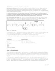
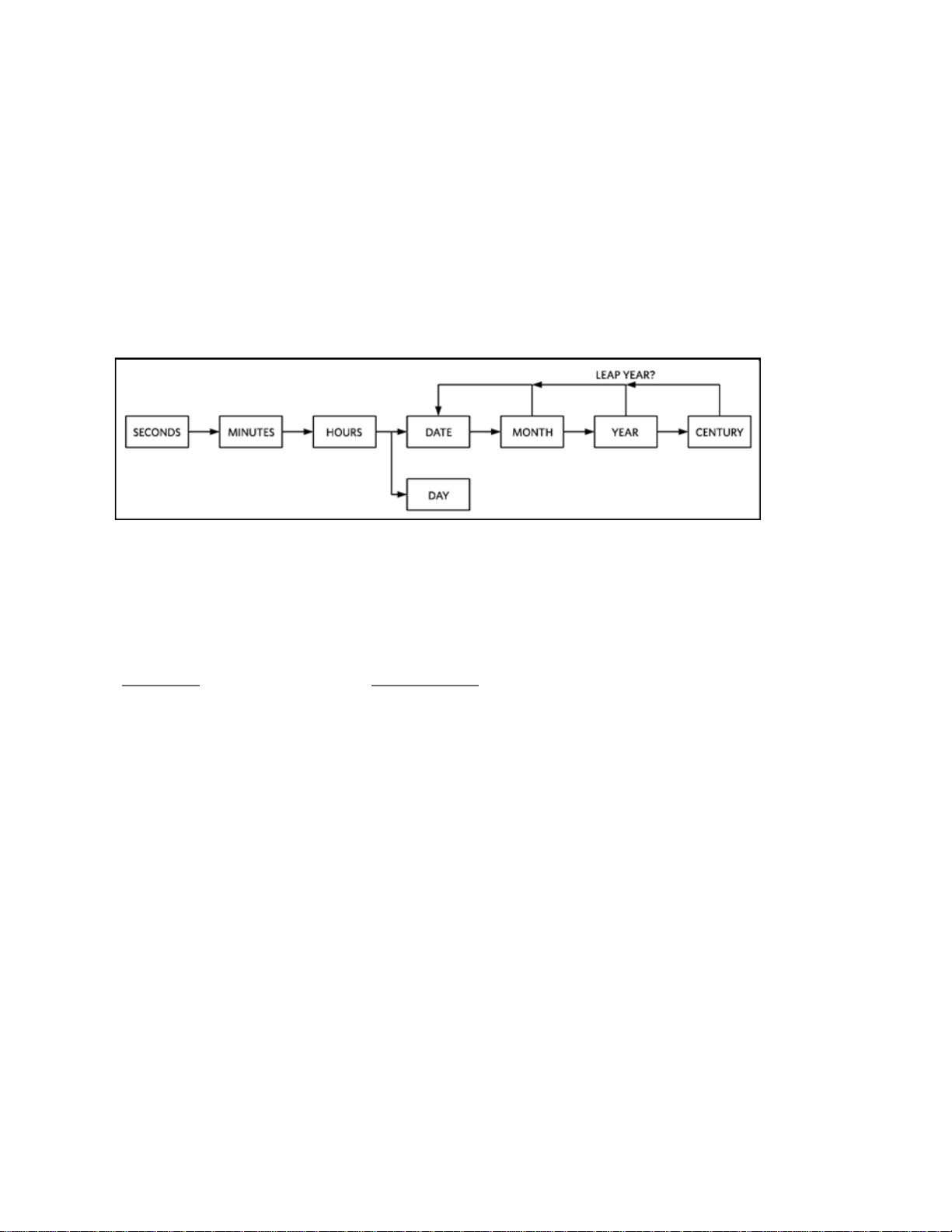
Load Initial Counter (Time) Values: Again referring to the product's specification and register map, the order of counter
loading or reading should be executed from least significant count to the most significant count. Figure 1 illustrates the
counter orientation and carry functions for a typical BCD-formatted real-time clock component.
Figure 1. RTC counter chain.
Whenever writing to the RTC, any write to the least significant counter byte resets the internal 1Hz chain, allowing the user
one full second before any timekeeping counter bits subsequently increment. This 1Hz reset action, as well as
synchronization techniques, are explained in further detail in the Time Synchronization section.
To facilitate ease of use, the registers are oriented in ascending weight and address order for your programming
convenience.
BCD Format
Hundredths of a Second (if so equipped)
Seconds
Minutes
Hours
Day of Week
Date
Month
Year
Century (if so equipped)
Binary (Seconds)
00h -> FFh = 0 -> 255.
00h -> FFh = 256. -> 65535.
00h -> FFh = 65536. -> 16777215.
00h -> FFh = 16777216. -> 4294967295.
Time Synchronization
To some users, the simple act of setting the clock (writing to the RTC) may accomplish the timekeeping accuracy goals for
the real-time clock in that application. Depending upon the care taken when initializing our device, an initial clock-set error
of a few seconds may be considered acceptable when weighed against the execution of the other tasks controlled by that
application.
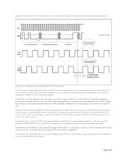
In other applications, it may be desired to synchronize the real-time clock with a known time standard, like WWV
1
. As
previously mentioned, writing to the least significant counter byte resets the 1Hz countdown chain. Figure 2 illustrates how
to reset the 1Hz countdown chain using an I
2
C Write sequence to the SECONDS register of a DS1340. The slave address
byte (D0h), register address (00h), and 'updated Seconds value' (03h), are being transmitted to the component. Two
Page 2 of 7
器件 Datasheet 文档搜索
AiEMA 数据库涵盖高达 72,405,303 个元件的数据手册,每天更新 5,000 多个 PDF 文件
