Datasheet 搜索 > 电压基准芯片 > TI(德州仪器) > LM431ACM3/NOPB 数据手册 > LM431ACM3/NOPB 其他数据使用手册 5/14 页

¥ 4.67
LM431ACM3/NOPB 其他数据使用手册 - TI(德州仪器)
制造商:
TI(德州仪器)
分类:
电压基准芯片
封装:
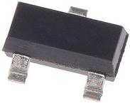
SOT-23-3
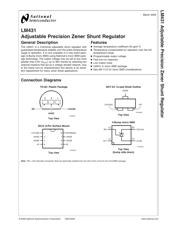
描述:
TEXAS INSTRUMENTS LM431ACM3/NOPB 电压基准, 精密, 分流 - 可调, LM431系列, 2.495V至36V, SOT-23-3
Pictures:
3D模型
符号图
焊盘图
引脚图
产品图
页面导航:
典型应用电路图在P4P8P9P10P11
封装尺寸在P12P13P14
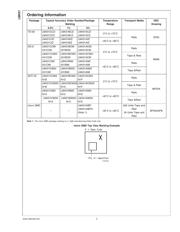
型号编码规则在P3
标记信息在P3
封装信息在P3
焊接温度在P5
功能描述在P2
技术参数、封装参数在P5
应用领域在P8P9P10P11
电气规格在P5P6P7P8

导航目录
LM431ACM3/NOPB数据手册
Page:
of 14 Go
若手册格式错乱,请下载阅览PDF原文件
Absolute Maximum Ratings (Note 2)
If Military/Aerospace specified devices are required,
please contact the National Semiconductor Sales Office/
Distributors for availability and specifications.
Storage Temperature Range −65˚C to +150˚C
Operating Temperature Range
Industrial (LM431xI) −40˚C to +85˚C
Commercial (LM431xC) 0˚C to +70˚C
Soldering Information
Infrared or Convection (20 sec.) 235˚C
Wave Soldering (10 sec.) 260˚C (lead temp.)
Cathode Voltage 37V
Continuous Cathode Current −10 mA to +150
mA
Reference Voltage −0.5V
Reference Input Current 10 mA
Internal Power Dissipation (Notes 3,
4)
TO-92 Package
SO-8 Package
SOT-23 Package
0.78W
0.81W
0.28W
micro SMD Package 0.30W
Operating Conditions
Min Max
Cathode Voltage V
REF
37V
Cathode Current 1.0 mA 100 mA
LM431
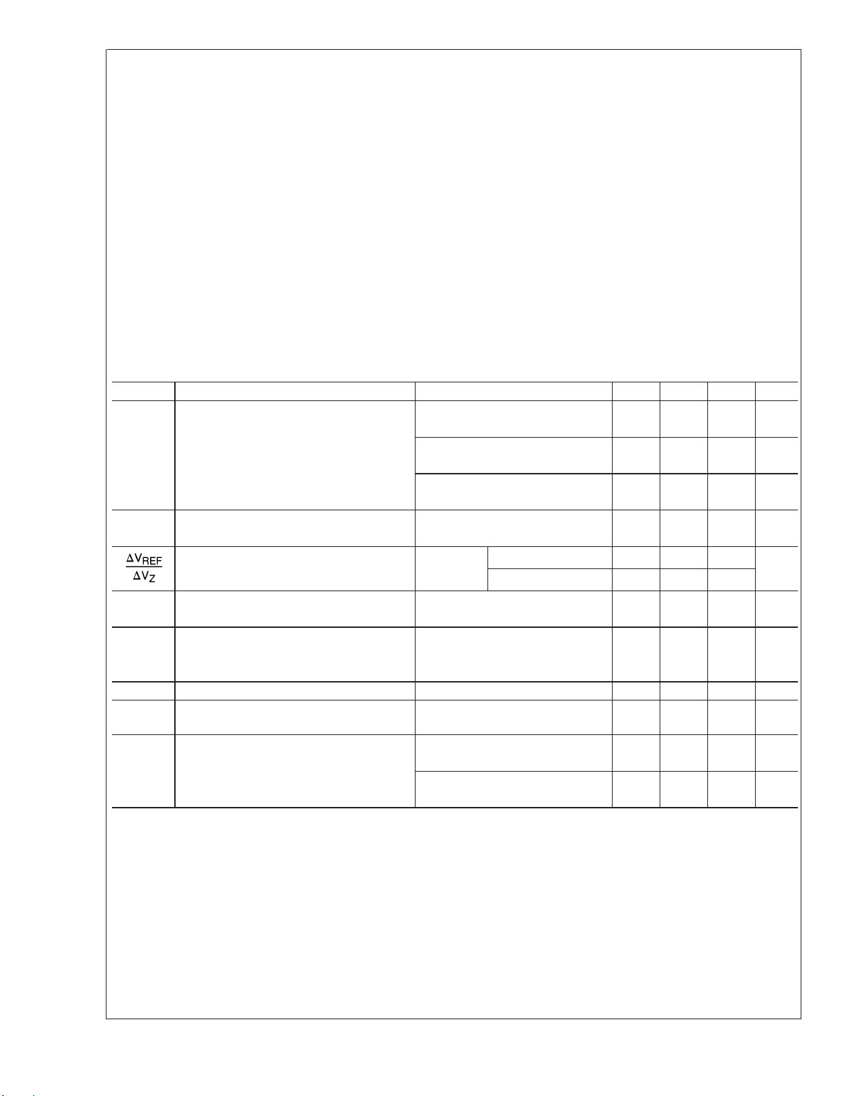
Electrical Characteristics
T
A
= 25˚C unless otherwise specified
Symbol Parameter Conditions Min Typ Max Units
V
REF
Reference Voltage V
Z
=V
REF
,I
I
= 10 mA 2.440 2.495 2.550 V
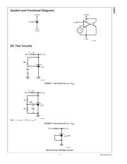
LM431A (Figure 1 )
V
Z
=V
REF
,I
I
= 10 mA 2.470 2.495 2.520 V
LM431B (Figure 1 )
V
Z
=V
REF
,I
I
= 10 mA 2.485 2.500 2.510 V
LM431C (Figure 1 )
V
DEV
Deviation of Reference Input Voltage Over V
Z
=V
REF
,I
I
= 10 mA, 8.0 17 mV
Temperature (Note 5) T
A
= Full Range (Figure 1 )
Ratio of the Change in Reference Voltage I
Z
=10mA V
Z
from V
REF
to 10V −1.4 −2.7
mV/V
to the Change in Cathode Voltage (Figure 2 )V
Z
from 10V to 36V −1.0 −2.0
I
REF
Reference Input Current R
1
=10kΩ,R
2
=
∞
, 2.0 4.0 µA
I
I
=10mA(Figure 2 )
∝
I
REF
Deviation of Reference Input Current over R
1
=10kΩ,R
2
=
∞
,
Temperature I
I
= 10 mA, 0.4 1.2 µA
T
A
= Full Range (Figure 2 )
I
Z(MIN)
Minimum Cathode Current for Regulation V
Z
=V
REF
(Figure 1 ) 0.4 1.0 mA
I
Z(OFF)
Off-State Current V
Z
= 36V, V
REF
=0V(Figure *NO
TARGET FOR fi* )
0.3 1.0 µA
r
Z
Dynamic Output Impedance (Note 6) V
Z
=V
REF
, LM431A, 0.75 Ω
Frequency=0Hz(Figure 1 )
V
Z
=V
REF
, LM431B, LM431C 0.50 Ω
Frequency=0Hz(Figure 1 )
Note 2: Absolute Maximum Ratings indicate limits beyond which damage to the device may occur. Electrical specifications do not apply when operating the device
beyond its rated operating conditions.
Note 3: T
J Max
= 150˚C.
Note 4: Ratings apply to ambient temperature at 25˚C. Above this temperature, derate the TO-92 at 6.2 mW/˚C, the SO-8 at 6.5 mW/˚C, the SOT-23 at 2.2 mW/˚C
and the micro SMD at 3mW/˚C.
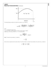
Note 5: Deviation of reference input voltage, V
DEV
, is defined as the maximum variation of the reference input voltage over the full temperature range.
LM431
www.national.com 4
器件 Datasheet 文档搜索
AiEMA 数据库涵盖高达 72,405,303 个元件的数据手册,每天更新 5,000 多个 PDF 文件
