Datasheet 搜索 > 放大器、缓冲器 > TI(德州仪器) > LM6181IM-8 数据手册 > LM6181IM-8 其他数据使用手册 2/28 页
 器件3D模型
¥ 1.688
LM6181IM-8 其他数据使用手册 - TI(德州仪器)
制造商:
TI(德州仪器)
分类:
放大器、缓冲器
封装:
SOIC-8
描述:
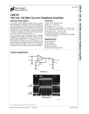
LM6181 100毫安, 100MHz的电流反馈放大器 LM6181 100 mA, 100 MHz Current Feedback Amplifier
Pictures:
3D模型
符号图
焊盘图
引脚图
产品图
页面导航:
典型应用电路图在P1P21P22P23
原理图在P20
封装尺寸在P26P27P28
型号编码规则在P25
功能描述在P1
技术参数、封装参数在P2P6
应用领域在P1P21P22P23
电气规格在P2P3P4P5P6P7P8P9P10P11P12P13
导航目录
LM6181IM-8数据手册
Page:
of 28 Go
若手册格式错乱,请下载阅览PDF原文件
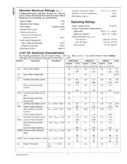
Absolute Maximum Ratings (Note 1)
If Military/Aerospace specified devices are required,
please contact the National Semiconductor Sales Office/
Distributors for availability and specifications.
Supply Voltage
±
18V
Differential Input Voltage
±
6V
Input Voltage
±
Supply Voltage
Inverting Input Current 15 mA
Soldering Information
Dual-In-Line Package (N)
Soldering (10 sec) 260˚C
Small Outline Package (M)
Vapor Phase (60 seconds) 215˚C
Infrared (15 seconds) 220˚C
Output Short Circuit (Note 7)
Storage Temperature Range −65˚C ≤ T
J
≤ +150˚C
Maximum Junction Temperature 150˚C
ESD Rating (Note 2)
±
3000V
Operating Ratings
Supply Voltage Range 7V to 32V
Junction Temperature Range (Note 3)
LM6181AM −55˚C ≤ T
J
≤ +125˚C
LM6181AI, LM6181I −40˚C ≤ T
J
≤ +85˚C
Thermal Resistance (θ
JA
, θ
JC
)
8-pin DIP (N) 102˚C/W, 42˚C/W
8-pin SO (M-8) 153˚C/W, 42˚C/W
16-pin SO (M) 70˚C/W, 38˚C/W
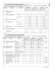
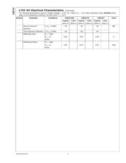
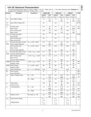
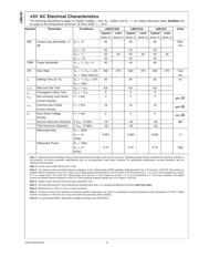
±
15V DC Electrical Characteristics
The following specifications apply for Supply Voltage =
±
15V, R
F
= 820Ω, and R
L
=1kΩ unless otherwise noted. Boldface
limits apply at the temperature extremes; all other limits T
J
= 25˚C.
Symbol Parameter Conditions LM6181AM LM6181AI LM6181I Units
Typical Limit Typical Limit Typical Limit
(Note 4) (Note 5) (Note 4) (Note 5) (Note 4) (Note 5)
V
OS
Input Offset Voltage 2.0 3.0 2.0 3.0 3.5 5.0 mV
4.0 3.5 5.5 max
TC
V
OS
Input Offset Voltage Drift 5.0 5.0 5.0 µV/˚C
I
B
Inverting Input Bias Current 2.0 5.0 2.0 5.0 5.0 10 µA
max
12.0 12.0 17.0
Non-Inverting Input Bias
Current
0.5 1.5 0.5 1.5 2.0 3.0
3.0 3.0 5.0
TC I
B
Inverting Input Bias Current
Drift
30 30 30 nA/˚C
Non-Inverting Input Bias 10 10 10
Current Drift
I
B
Inverting Input Bias Current V
S
=
±
4.5V,
±
16V 0.3 0.5 0.3 0.5 0.3 0.75 µA/V
max
PSR Power Supply Rejection 3.0 3.0 4.5
Non-Inverting Input Bias
Current
V
S
=
±
4.5V,
±
16V 0.05 0.5 0.05 0.5 0.05 0.5
Power Supply Rejection 1.5 1.5 3.0
I
B
Inverting Input Bias Current −10V ≤ V
CM
≤ +10V 0.3 0.5 0.3 0.5 0.3 0.75
CMR Common Mode Rejection 0.75 0.75 1.0
Non-Inverting Input Bias
Current
−10V ≤ V
CM
≤ +10V 0.1 0.5 0.1 0.5 0.1 0.5
Common Mode Rejection 0.5 0.5 0.5
CMRR Common Mode Rejection
Ratio
−10V ≤ V
CM
≤ +10V 60 50 60 50 60 50 dB
50 50 50 min
PSRR Power Supply Rejection Ratio V
S
=
±
4.5V,
±
16V 80 70 80 70 80 70 dB
70 70 65 min
R
O
Output Resistance A
V
= −1, f = 300
kHz
0.2 0.2 0.2 Ω
LM6181
www.national.com 2
器件 Datasheet 文档搜索
AiEMA 数据库涵盖高达 72,405,303 个元件的数据手册,每天更新 5,000 多个 PDF 文件
