Datasheet 搜索 > 接口芯片 > Maxim Integrated(美信) > MAX3421EETJ 数据手册 > MAX3421EETJ 其他数据使用手册 4/10 页


¥ 14.089
MAX3421EETJ 其他数据使用手册 - Maxim Integrated(美信)
制造商:
Maxim Integrated(美信)
分类:
接口芯片
描述:
USB外设/主机控制器,SPI接口 USB Peripheral/Host Controller with SPI Interface
Pictures:
3D模型
符号图
焊盘图
引脚图
产品图
页面导航:
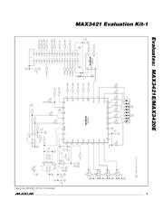
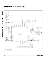
原理图在P3P5P6
型号编码规则在P1
功能描述在P1
导航目录
MAX3421EETJ数据手册
Page:
of 10 Go
若手册格式错乱,请下载阅览PDF原文件
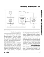
User Notes:
1) The MAX3420E connects to USB Type B connector
J5, while the MAX3421E connects both to USB Type
A connector J1 and to USB Type B connector J2.
The MAX3421E, therefore, can be connected as a
host (J1) or a peripheral (J2).
2) The user system must supply 3.3V on J4 pins 1-2 to
power the board. The 3.3V supply should be capa-
ble of providing 100mA.
3) The RES pins connect directly to the MAX3420E/
MAX3421E reset pins. It must be driven high for the
chip to operate.
4) When operating the MAX3421E as a host controller,
the user system must provide 5V power on J4 pins
33-34, or on J3 pin 3. This voltage connects to the
V
BUS
pin of USB Type A connector J1 through a
current-limiting switch. The user system must supply
enough current to power any USB device plugged
into J1. The current-limiting switch (a MAX4793) lim-
its the V
BUS
current to 300mA.
5) Keep leads to the target system short (under 6in).
Long leads and insufficient grounds can lead to sig-
nal ringing and erratic operation.
6) When using the MAX3421E as a host, the user
program must set the MAX3421E GPO7 pin high
to turn on the V
BUS
switch (U3) that supplies 5V to
the USB Type A connector J1. Note that the
MAX3421E output port also drives the 7-segment
readout using GPO[6:0]. Therefore, the code that
updates the 7-segment readout must preserve the
bit 7 setting, and the code that turns V
BUS
on and
off must preserve the bits [6:0] settings. This is easi-
ly accomplished by first reading the states of the
output bits, changing only the needed bits, then
writing them back.
Evaluates: MAX3421E/MAX3420E
MAX3421 Evaluation Kit-1
4 _______________________________________________________________________________________
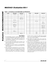
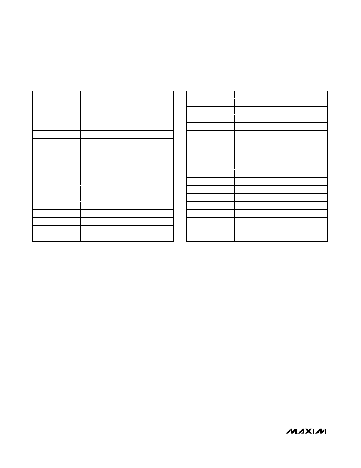
Table 1. J4 Interface to the MAX3420E and MAX3421E
J4 PIN MAX3420E MAX3421E
1 3.3V (in) 3.3V (in)
2——
3——
4 — SCK (in)
5 — MISO (out)
6 SCK (in) —
7——
8 MISO (out) —
9——
10 MOSI (in) —
11 GPX (out) —
12 SS (in) —
13 — —
14 — —
15 — —
16 RES (in) —
17 — —
18 — RES (in)
J4 PIN MAX3420E MAX3421E
19 — —
20 — —
21 — —
22 — INT (out)
23 — —
24 — —
25 INT (out) —
26 — SS (in)
27 — SCK (in)
28 — —
29 — MISO (out)
30 — GPX (out)
31 — MOSI (in)
32 — —
33 — 5V (in)
34 — 5V (in)
35 GND GND
36 GND GND
器件 Datasheet 文档搜索
AiEMA 数据库涵盖高达 72,405,303 个元件的数据手册,每天更新 5,000 多个 PDF 文件
