Datasheet 搜索 > 计数器 > ON Semiconductor(安森美) > MC14526BCP 数据手册 > MC14526BCP 其他数据使用手册 2/10 页
 器件3D模型
¥ 0
MC14526BCP 其他数据使用手册 - ON Semiconductor(安森美)
制造商:
ON Semiconductor(安森美)
分类:
计数器
封装:
PDIP-16
描述:
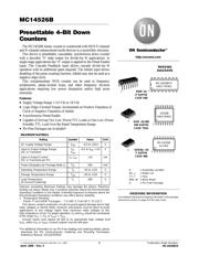
可预置4位计数器 Presettable 4-Bit Down Counters
Pictures:
3D模型
符号图
焊盘图
引脚图
产品图
页面导航:
导航目录
MC14526BCP数据手册
Page:
of 10 Go
若手册格式错乱,请下载阅览PDF原文件

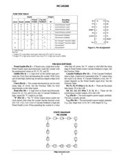
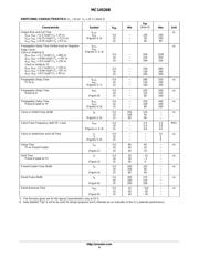
Figure 1. Pin Assignment
13
14
15
16
9
10
11
125
4
3
2
1
8
7
6
0"
CF
P2
Q2
V
DD
Q1
RESET
P1
INHIBIT
PE
P3
Q3
V
SS
CLOCK
P0
MC14526B
http://onsemi.com
2
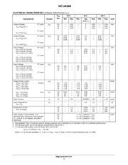
FUNCTION TABLE
Inputs Output
Resulting
Function
Clock Reset Inhibit
Preset
Enable
Cascade
Feedback
“0”
X
X
X
H
H
H
X
X
X
L
H
X
L
L
H
L
H
H
Asynchronous reset*
Asynchronous reset
Asynchronous reset
X L X H X L Asynchronous preset
L
L
L
H L
L
X
X
L
L
Decrement inhibited
Decrement inhibited
H
H
L
L
L
L
L
L
L
L
L
L
L
L
L
L
L
L
L
L
No change** (inactive edge)
No change** (inactive edge)
Decrement**
Decrement**
X = Don’t Care
NOTES:
** Output “0” is low when reset goes high only it PE and CF are low.
** Output “0” is high when reset is low, only if CF is high and count is 0000.
PIN DESCRIPTIONS
Preset Enable (Pin 3) — If Reset is low, a high level on the
Preset Enable input asynchronously loads the counter with
the programmed values on P0, P1, P2, and P3.
Inhibit (Pin 4) — A high level on the Inhibit input pre−
vents the Clock from decrementing the counter. With Clock
(pin 6) held high, Inhibit may be used as a negative edge clock
input.
Clock (Pin 6) — The counter decrements by one for each
rising edge of Clock. See the Function Table for level
requirements on the other inputs.
Reset (Pin 10) — A high level on Reset asynchronously
forces Q0, Q1, Q2, and Q3 low and, if Cascade Feedback is
high, causes the “0” output to go high.
“0” (Pin 12) — The “0” (Zero) output issues a pulse one
clock period wide when the counter reaches terminal count
(Q0 = Q1 = Q2 = Q3 = low) if Cascade Feedback is high and
Preset Enable is low. When presetting the counter to a value
other than all zeroes, the “0” output is valid after the rising
edge of Preset Enable (when Cascade Feedback is high). See
the Function Table.
Cascade Feedback (Pin 13) — If the Cascade Feedback
input is high, a high level is generated at the “0” output when
the count is all zeroes. If Cascade Feedback is low, the “0”
output depends on the Preset Enable input level. See the
Function Table.
P0, P1, P2, P3 (Pins 5, 11, 14, 2) — These are the preset
data inputs. P0 is the LSB.
Q0, Q1, Q2, Q3 (Pins 7, 9, 15, 1) — These are the
synchronous counter outputs. Q0 is the LSB.
V
SS
(Pin 8) — The most negative power supply potential.
This pin is usually ground.
V
DD
(Pin 16) — The most positive power supply potential.
V
DD
may range from 3.0 to 18 V with respect to V
SS
.
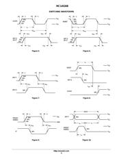
STATE DIAGRAM
MC14526B
43210
15
14
13
12 11 10 9 8
7
6
5
器件 Datasheet 文档搜索
AiEMA 数据库涵盖高达 72,405,303 个元件的数据手册,每天更新 5,000 多个 PDF 文件
