Datasheet 搜索 > 微控制器 > Microchip(微芯) > PIC16F1946-I/MR 数据手册 > PIC16F1946-I/MR 其他数据使用手册 3/13 页
 器件3D模型
¥ 6.983
PIC16F1946-I/MR 其他数据使用手册 - Microchip(微芯)
制造商:
Microchip(微芯)
分类:
微控制器
封装:
QFN-64
描述:
PIC16F1946/1947 8 位闪存微控制器Microchip 的 PIC16F 系列微控制器 8 位 MCU,将 Microchip 的 PIC® 体系架构融入到引脚和封装选件中,从节省空间的 14 引脚设备到功能丰富的 64 引脚设备。 带有基线、中级或增强型中级体系架构的设备提供多种不同的外围设备组合,可谓设计人员提供灵活性,并为应用提供选择。 PIC16F1946/1947 系列微控制器基于 Microchip 的增强型中级内核,带 16 层深硬件堆栈和 49 个指令。 这些 MCU 提供高达 8 个 MIP、28 千字节程序存储器、1024 字节 RAM 和 256 字节数据 EEPROM。 板载可配置振荡器,精确度为 ±1%。### 微控制器功能最大 32 MHz CPU 速度 49 个指令 16 级硬件堆栈 32 MHz 内部振荡器 - 可选频率范围 32 MHz 至 31 kHz 54 个输入/输出引脚 nanoWatt XLP 技术 通电重置 (POR) 通电计时器 (PWRT) 振荡器启动计时器 (OST) 掉电重置 (BOR) 监控器计时器 (WDT) 低电压编程 (LVP) 在线串行编程 (ICSP) 在线调试 (ICD) ### 外设集成 LCD 控制器 - 184 段 10 位模拟到数字转换器 (ADC) - 17 通道 mTouchTM 电容性传感器模块 - 17 通道 两个捕捉/比较/PWM (CCP) 模块 三个增强型捕获/比较/PWM (ECCP) 模块 三个比较器 四个 8 位计时器 一个 16 位计时器 两个主同步串行端口 (MSSP),带 SPI 和 I2C 两个增强型通用同步异步接收器发射器 (EUSART) 固定电压参考 (FVR) SR 闩锁 ### PIC16 微控制器展开
Pictures:
3D模型
符号图
焊盘图
引脚图
产品图
PIC16F1946-I/MR数据手册
Page:
of 13 Go
若手册格式错乱,请下载阅览PDF原文件
2010-2014 Microchip Technology Inc. DS80000497G-page 3
PIC16(L)F1946/1947
Silicon Errata Issues
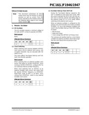
1. Module: Oscillator
1.1 HS Oscillator
The HS oscillator requires a minimum voltage of
3.0 volts (at 65°C or less) to operate at 20 MHz.
Work around
None.
Affected Silicon Revisions
1.2 Clock Switching
When switching clock sources between INTOSC
clock source and an external clock source, one
corrupted instruction may be executed after the
switch occurs.
This issue affects Two-Speed Start-Up and Fail-
Safe Clock Monitor operation.
Work around
When switching from an external oscillator clock
source, first switch to 16 MHz HFINTOSC. Once
running at 16 MHz HFINTOSC, configure IRCF to
run at desired internal oscillator frequency.
When clock switching from an INTOSC to an
external oscillator clock source, first switch from
the desired INTOSC frequency to HFINTOSC
High-Power mode (8 MHz or 16 MHz). Once
running from HFINTOSC, switch to the external
oscillator clock source.
Affected Silicon Revisions
1.3 Oscillator Start-up Timer (OST) bit
During the Two-Speed Start-up sequence, the
OST is enabled to count 1024 clock cycles. After
the count is reached, the OSTS bit is set, the sys-
tem clock is held low until the next falling edge of
the external crystal (LP, XT or HS mode), before
switching to the external clock source.
When an external oscillator is configured as the
primary clock and Fail-Safe Clock mode is enabled
(FCMEN = 1), any of the following conditions will
result in the Oscillator Start-up Timer (OST) failing
to restart:
•MCLR
Reset
• Wake from Sleep
• Clock change from INTOSC to Primary Clock
This anomaly will manifest itself as a clock failure
condition for external oscillators which take longer
than the clock failure time-out period to start.
Work around
None.
Affected Silicon Revisions
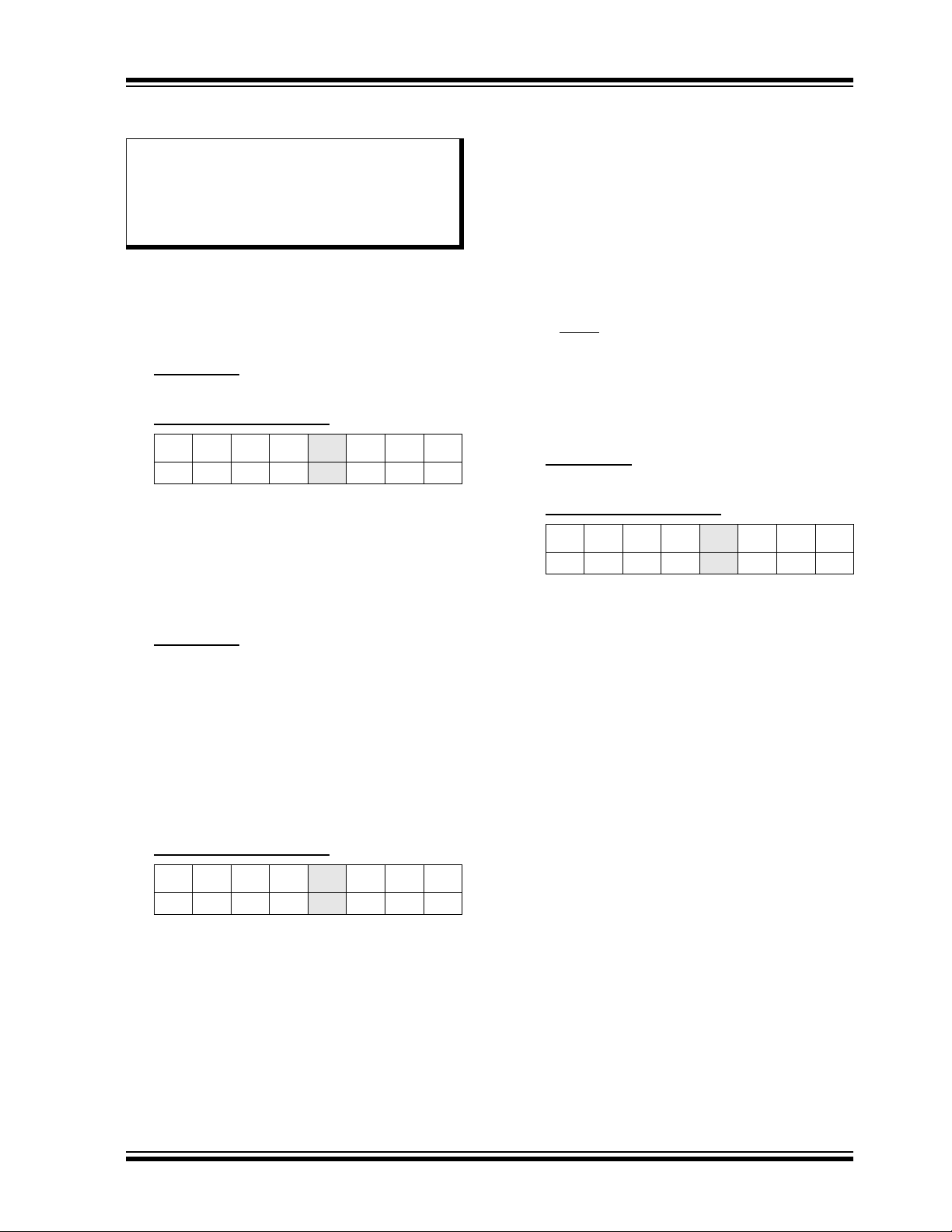
Note: This document summarizes all silicon
errata issues from all revisions of silicon,
previous as well as current. Only the
issues indicated by the shaded column in
the following tables apply to the current
silicon revision (A6).
A2 A3 A4 A5 A6
X
A2 A3 A4 A5 A6
X X XX
A2 A3 A4 A5 A6
X X XX
器件 Datasheet 文档搜索
AiEMA 数据库涵盖高达 72,405,303 个元件的数据手册,每天更新 5,000 多个 PDF 文件
