Datasheet 搜索 > 8位微控制器 > Microchip(微芯) > PIC16F723-E/SO 数据手册 > PIC16F723-E/SO 其他数据使用手册 3/10 页
 器件3D模型
¥ 4.668
PIC16F723-E/SO 其他数据使用手册 - Microchip(微芯)
制造商:
Microchip(微芯)
分类:
8位微控制器
封装:
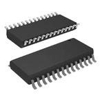
SOIC-28
描述:
PIC16 8 位 微控制器 带 7 KB 闪存 28 引脚 SOIC 封装
Pictures:
3D模型
符号图
焊盘图
引脚图
产品图
页面导航:
技术参数、封装参数在P6
电气规格在P6
导航目录
PIC16F723-E/SO数据手册
Page:
of 10 Go
若手册格式错乱,请下载阅览PDF原文件
2008-2013 Microchip Technology Inc. DS80000382K-page 3
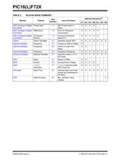
PIC16(L)F72X
Silicon Errata Issues
1. Module: ADC (Analog-to-Digital
Converter)
1.1 ADC Power-down in Sleep
The ADC module incorrectly fails to power-down
after a conversion if the device is in Sleep and the
ADC interrupt is disabled. The proper operation is
to power the ADC off after the conversion is
complete if the device is sleeping and the ADC
interrupt is disabled.
Work around
Use the ADC conversion complete interrupt
(ADIF) to wake-up and explicitly shut down the
ADC by clearing the ADON bit.
Affected Silicon Revisions
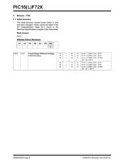
1.2 Error on Infrequent Conversions
The offset error incorrectly exceeds the data sheet
specifications if time between conversions is
longer than 10 ms. If the time between
conversions is greater than 10 ms, the offset error
is 1 LSb typical and 3.3 LSb maximum.
Work around
The time dependent error is insignificant when the
time between conversions is less than 10 ms.
When the time between conversions is greater
than 10 ms, take two back-to-back ADC
conversions and discard the results of the first
conversion.
Affected Silicon Revisions
1.3 Incorrect Conversion below 0°C
In some devices, the ADC may improperly convert
if the temperature is below 0°C and the ADC clock
source is set to F
OSC/8, FOSC/16, FOSC/32, FOSC/
64.
Work around
Set the ADC clock source to FOSC/2, FOSC/4 or
RC.
Affected Silicon Revisions
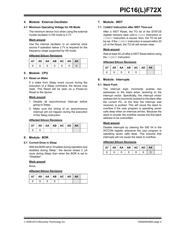
2. Module: Timer1
2.1 Operation above 90°C
The Timer1 oscillator does not operate above
90C.
Work around
None.
Affected Silicon Revisions
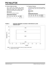
3. Module: Internal Oscillator
3.1 Frequency Shift on Reset
The internal oscillator module may experience a
±1% frequency shift after a Reset. The frequency
shift is not consistent and could cause the oscilla-
tor to operate outside of the 2% specification.
Work around
To minimize the chances of experiencing the
frequency shift, the following steps should be
taken:
1. Operate the internal oscillator at 8 MHz or
2MHz.
2. Use an external pull-up on MCLR
or use
internal MCLR
mode.
3. Disable the Power Reset Timer (PWRT).
4. The bypass capacitor and the Voltage
Regulator Capacitor (V
CAP) should be used
appropriately to minimize noise in the device.
Affected Silicon Revisions
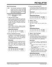
Note: This document summarizes all silicon
errata issues from all revisions of silicon,
previous as well as current. Only the
issues indicated by the shaded column in
the following tables apply to the current
silicon revision (as applicable).
A7 A9 AA AB AC AD AK
XXXX
A7 A9 AA AB AC AD AK
XXXXX
A7 A9 AA AB AC AD AK
XXXXX
A7 A9 AA AB AC AD AK
XXXXXX
X
A7 A9 AA AB AC AD
AK
X
器件 Datasheet 文档搜索
AiEMA 数据库涵盖高达 72,405,303 个元件的数据手册,每天更新 5,000 多个 PDF 文件
