Datasheet 搜索 > 8位微控制器 > Microchip(微芯) > PIC16F723-E/SO 数据手册 > PIC16F723-E/SO 其他数据使用手册 5/10 页
 器件3D模型
¥ 4.668
PIC16F723-E/SO 其他数据使用手册 - Microchip(微芯)
制造商:
Microchip(微芯)
分类:
8位微控制器
封装:
SOIC-28
描述:
PIC16 8 位 微控制器 带 7 KB 闪存 28 引脚 SOIC 封装
Pictures:
3D模型
符号图
焊盘图
引脚图
产品图
页面导航:
技术参数、封装参数在P6
电气规格在P6


导航目录
PIC16F723-E/SO数据手册
Page:
of 10 Go
若手册格式错乱,请下载阅览PDF原文件
2008-2013 Microchip Technology Inc. DS80000382K-page 5
PIC16(L)F72X
4. Module: External Oscillator
4.1 Minimum Operating Voltage for HS Mode
The minimum device V
DD when using the external
crystal oscillator in HS mode is 2.7V.
Work around
Use the internal oscillator or an external clock
source if operation below 2.7V is required for the
frequency range supported by HS mode.
Affected Silicon Revisions
5. Module: CPU
5.1 Reset on Wake
If a wake from Sleep event occurs during the
execution of a Sleep command, the device may
reset. This Reset will be seen as a Power-on
Reset to the device.
Work around
1. Disable all asynchronous interrupt before
going to Sleep.
2. Make sure the timing of an asynchronous
interrupt will not happen during the execution
of the Sleep instruction.
Affected Silicon Revisions
6. Module: BOR
6.1 Current Draw in Sleep
With the BOR set to “Enabled during operation and
disabled during Sleep”, the device draws 2 A
more during Sleep than when the BOR is set to
“Disabled”.
Work around
None.
Affected Silicon Revisions
7. Module: WDT
7.1 CLRWDT Instruction after WDT Time-out
After a WDT Reset, the TO bit of the STATUS
register remains clear until a SLEEP instruction or
CLRWDT instruction is issued, then, the TO bit will
be set. If the CLRWDT instruction is issued within 20
S of the Reset, the TO bit will remain clear.
Work around
Wait at least 20 S after a WDT Reset before using
the CLRWDT instruction.
Affected Silicon Revisions
8. Module: Interrupts
8.1 Stack Push
The interrupt logic incorrectly pushes two
addresses to the stack when vectoring to the
interrupt vector. Specifically, the interrupt vector
address 0x4 is incorrectly pushed to the stack after
the current PC, at the time the interrupt was
received, is pushed. This will cause the stack to
overflow if the user program is operating seven
calls deep when an interrupt arrives. Because the
stack is circular, the overflow causes the first stack
address to be overwritten.
Work around
Disable interrupts by clearing the GIE bit in the
INTCON register whenever the user program is
operating seven calls deep. This ensures that
interrupts will not cause the stack to overflow.
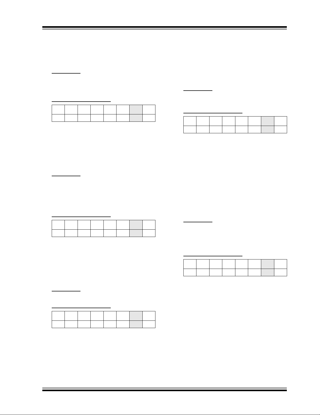
Affected Silicon Revisions
A7 A9 AA AB AC AD AK
XXXXXX
X
A7 A9 AA AB AC AD
AK
XX
A7 A9 AA AB AC AD AK
XXXX
A7 A9 AA AB AC AD AK
XXXXX
A7 A9 AA AB AC AD AK
XXXXXX
X
器件 Datasheet 文档搜索
AiEMA 数据库涵盖高达 72,405,303 个元件的数据手册,每天更新 5,000 多个 PDF 文件
