Datasheet 搜索 > 微控制器 > TI(德州仪器) > TMS320F2811PBKA 数据手册 > TMS320F2811PBKA 其他数据使用手册 5/32 页
 器件3D模型
¥ 179.154
TMS320F2811PBKA 其他数据使用手册 - TI(德州仪器)
制造商:
TI(德州仪器)
分类:
微控制器
封装:
LQFP-128
描述:
TEXAS INSTRUMENTS TMS320F2811PBKA 芯片, 数字信号处理/控制器 带闪存, 32位
Pictures:
3D模型
符号图
焊盘图
引脚图
产品图
页面导航:
导航目录
TMS320F2811PBKA数据手册
Page:
of 32 Go
若手册格式错乱,请下载阅览PDF原文件
TMS320F28xx
和
TMS320F28xxx DSCs
的硬件设计指南
5ZHCA065–2008
年
8
月
www.ti.com.cn
C1
C2
X1 X2
C(Load)�=
C1�x�C2
C1�+�C2
TMS320F28x
3.1.1.2 Using External Oscillator
www.ti.com
Handling of Different Hardware Building Blocks
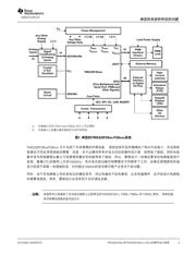
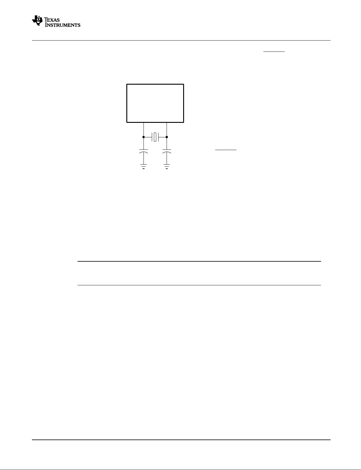
Figure 3 shows the external circuitry and connections required for using the internal oscillator, along with
the equation defining the relationship between the manufacturer’s specified crystal load capacitance
C
LOAD
, formed by two external capacitors C1 and C2. The external clock mode control inputs specify
whether the internal oscillator is enabled or disabled. When the internal oscillator is used, choose the
clock-mode selection that enables the internal oscillator.
Figure 3. Typical Crystal Circuit
The effective load capacitance, C
LOAD
, appears to the crystal circuit as the series combination of C1 and
C2. Correct C
LOAD
is important for proper operating frequency. Crystals are available with a variety of
C
LOAD
values. However, the internal DSC oscillator will not start and run reliably with too high or too low of
a C
LOAD
value. For more information, check the specifications from the crystal vendor’s data sheets. It is
recommended to select a fundamental mode parallel resonant type crystal having a C
LOAD
of around 12
pF and ESR of 30 to 60 Ω.
The actual discrete values required for C1 and C2 are generally up to 5 pf below the calculated load
capacitance due to PCB traces and the DSC input pin's stray capacitances; the board layout is quite
important. If precise frequency control is required, the exact discrete capacitor values can be determined
by varying the capacitor values and performing precision frequency measurements using a frequency
counter.
Note: It is recommended that you have the resonator/crystal vendor characterize the operation of
their device with the DSC chip. The resonator/crystal vendor has the equipment and
expertise to tune the tank circuit. The vendor can also advise you regarding the proper tank
component values for proper start-up and stability over the entire operating range.
To select a proper external oscillator, consider the specifications such as frequency, stability, aging,
voltage sensitivity, rise and fall time, duty cycle, and signal levels. Some designs may have to consider
clock jitter. Note that only F280x and F28xxx devices can accept an external clock signal having an
amplitude of V
DD
(1.8 V/1.9 V) or 3.3 V. The clock signal for F281x parts should toggle between 0 and
V
DD
.
SPRAAS1A– August 2008 Hardware Design Guidelines for TMS320F28xx and TMS320F28xxx DSCs 5
Submit Documentation Feedback
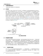
图
3.
典型的晶振电路
图
3
显示了利用晶振来连接的外部电路,上拉电容的大小根据等式而定。
它和两个外部电容有关。外部时钟的模式控制着是否使用内部的晶振。当使用内部的振荡器时,选择让内部
的晶振可用的时钟模式。
有效的负载电容,
C
LOAD
,在振荡电路中是
C1
和
C2
并联的等效电容,正确的有效负载电容对于正确的运行频
率是非常重要的,对于不同的负载电容的值,都有不同的晶振与其对应,但是,内部的数字控制器振荡器对
于太高或太低的负载电容是没法工作的,可以从晶振的厂商的数据手册得到更多的信息。并联谐振模式需要
的负载电容大概是
12pF
,等效电阻是
30
-
60W
。由于
PCB
板布局和数字控制器焊锡的兼容性问题,有效的
C1
和
C2
的值一般不大于
5 pf
,布局电路板也是非常重要的方面。如果想要得到准确的频率控制器,那么准确
的离散电容值,要根据利用频率计数器测量的电容和频率的准确关系来定。
确实需要振荡器和数字控制芯片的连接参数关系。晶振或共振器的提供厂商都有专门的设备和知识来调整
振荡回路,并且会给用户提供正确搭建整个电路工作范围的相关器件值。
注释:
利用外部振荡器
为了选择合适的外部振荡器,需要考虑频率、稳定性、时效性、上升和下降时间、占空比、信号电平等问
题,设计者必须考虑到时钟偏差的问题。必须注意事项是只有
F28xxx
芯片能接收
V
DD
(1.8 V/1.9 V)
或者
3.3 V
的外部时钟的电压,
F281x
时钟信号应该在
0
和电压值之间变换。
3.1.1.2
C1
C2
X1 X2
C(Load)�=
C1�x�C2
C1�+�C2
TMS320F28x
3.1.1.2 Using External Oscillator
www.ti.com
Handling of Different Hardware Building Blocks
Figure 3 shows the external circuitry and connections required for using the internal oscillator, along with
the equation defining the relationship between the manufacturer’s specified crystal load capacitance
C
LOAD
, formed by two external capacitors C1 and C2. The external clock mode control inputs specify
whether the internal oscillator is enabled or disabled. When the internal oscillator is used, choose the
clock-mode selection that enables the internal oscillator.
Figure 3. Typical Crystal Circuit
The effective load capacitance, C
LOAD
, appears to the crystal circuit as the series combination of C1 and
C2. Correct C
LOAD
is important for proper operating frequency. Crystals are available with a variety of
C
LOAD
values. However, the internal DSC oscillator will not start and run reliably with too high or too low of
a C
LOAD
value. For more information, check the specifications from the crystal vendor’s data sheets. It is
recommended to select a fundamental mode parallel resonant type crystal having a C
LOAD
of around 12
pF and ESR of 30 to 60 Ω.
The actual discrete values required for C1 and C2 are generally up to 5 pf below the calculated load
capacitance due to PCB traces and the DSC input pin's stray capacitances; the board layout is quite
important. If precise frequency control is required, the exact discrete capacitor values can be determined
by varying the capacitor values and performing precision frequency measurements using a frequency
counter.
Note: It is recommended that you have the resonator/crystal vendor characterize the operation of
their device with the DSC chip. The resonator/crystal vendor has the equipment and
expertise to tune the tank circuit. The vendor can also advise you regarding the proper tank
component values for proper start-up and stability over the entire operating range.
To select a proper external oscillator, consider the specifications such as frequency, stability, aging,
voltage sensitivity, rise and fall time, duty cycle, and signal levels. Some designs may have to consider
clock jitter. Note that only F280x and F28xxx devices can accept an external clock signal having an
amplitude of V
DD
(1.8 V/1.9 V) or 3.3 V. The clock signal for F281x parts should toggle between 0 and
V
DD
.
SPRAAS1A– August 2008 Hardware Design Guidelines for TMS320F28xx and TMS320F28xxx DSCs 5
Submit Documentation Feedback
不同硬件模块的设计
器件 Datasheet 文档搜索
AiEMA 数据库涵盖高达 72,405,303 个元件的数据手册,每天更新 5,000 多个 PDF 文件
