Datasheet 搜索 > 开发套件 > TI(德州仪器) > TSC2004EVM 数据手册 > TSC2004EVM 其他数据使用手册 4/24 页

¥ 365.374
TSC2004EVM 其他数据使用手册 - TI(德州仪器)
制造商:
TI(德州仪器)
分类:
开发套件
描述:
TEXAS INSTRUMENTS TSC2004EVM 评估模块, TSC2004EVM
Pictures:
3D模型
符号图
焊盘图
引脚图
产品图
页面导航:
原理图在P6P17P18P19
应用领域在P24
导航目录
TSC2004EVM数据手册
Page:
of 24 Go
若手册格式错乱,请下载阅览PDF原文件

www.ti.com
4.1 TSC Power
4.2 Stand-Alone Operation
4.3 USB-MODEVM Interface Power
4.4 Reference Voltage
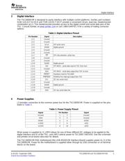
Power Supplies
Power for the TSC2005 SNSVDD, analog, and sense driver power supply, can be supplied either from
+1.8 V or from +3.3 V, selected by setting JMP2. When the shunt is installed on JMP2 pins 1-2, power
SNSVDD come from J3.7 (+1.8VD) through an inductor to prevent digital noise from coupling into the
analog supply. When the shunt is installed on JMP2 pins 2-3, power SNSVDD come from J3.9 (+3.3VD)
through an inductor to prevent digital noise from coupling into the analog supply. Also, the user can
remove the shunt and connect an external power supply to the pin 2 of JMP2 if other than 1.8-V or 3.3-V
power is used. By default factory setting, SNSVDD is set to +3.3VD, shunt on JMP2 pins 1-2..
Power for the TSC2005 IOVDD and digital IO power supply is selected using JMP4, either 1.8V or 3.3V or
SNSVDD. When JMP4 is in the default factory condition (shunt on pins 3-4), power to the TSC is
connected to the same power supply as SNSVDD.
When used as a stand-alone EVM, the analog power can be applied to TP1 (SNSVDD) and referenced to
TP4 (GND). IOVDD can be applied to TP2 (IOVDD) and referenced to TP4.
CAUTION
Verify that all power supplies are within the safe operating limits shown on the
TSC2005 data sheet before applying power to the EVM.
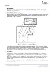
The USB-MODEVM Interface Board can be powered from several different sources:
• USB
• 6-VDC to 10-VDC AC/DC wall supply (not included)
• Laboratory power supply
When powered from the USB connection, JMP6 should have a shunt from pins 1-2 (this is the default
factory configuration). When powered from 6-VDC to 10-VDC, either through the J8 terminal block or J9
barrel jack, JMP6 should have a shunt installed on pins 2-3. If power is applied in any of these ways,
onboard regulators generate the required supply voltages and no further power supplies are necessary.
If laboratory supplies are used to provide the individual voltages required by the USB-MODEVM Interface
Board, JMP6 should have no shunt installed. Voltages then are applied to J2 (+5VA), J3 (+5VD), J4
(+1.8VD), and J5 (+3.3VD). The +1.8VD and +3.3VD can also be generated on the board by the onboard
regulators from the +5VD supply; to enable this, the SW1 switches need to be set in the ON position
(lower position, looking at the board with text reading right-side up) to enable the regulators. If +1.8VD and
+3.3VD are supplied externally, disable the onboard regulators by placing the SW1 switches in the OFF
position.
Each power-supply voltage has an LED (D1–D7) which lights when the power supplies are active.
The reference voltage can be provided on the board from SNSVDD on TSC2005EVM. An external
reference can be supplied through J1 pin 20 referenced to analog ground (J1 pin 18 on the
TSC2005EVM), or through TP3 (VREF) referenced on TP4(GND) on the TSC2005EVM. JMP1 must be
set correspondingly, as shown in Table 4 .
TSC2005EVM and TSC2005EVM-PDK4 SLAU191 – September 2006
Submit Documentation Feedback
器件 Datasheet 文档搜索
AiEMA 数据库涵盖高达 72,405,303 个元件的数据手册,每天更新 5,000 多个 PDF 文件
