Datasheet 搜索 > CAN芯片 > ADI(亚德诺) > ADM3054BRWZ 数据手册 > ADM3054BRWZ 产品设计参考手册 1/14 页
 器件3D模型
¥ 288.66
ADM3054BRWZ 产品设计参考手册 - ADI(亚德诺)
制造商:
ADI(亚德诺)
分类:
CAN芯片
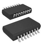
封装:
SOIC-16
描述:
ANALOG DEVICES ADM3054BRWZ. 芯片, CAN总线收发器, 16-SOIC
Pictures:
3D模型
符号图
焊盘图
引脚图
产品图
页面导航:
原理图在P12
应用领域在P10
导航目录
ADM3054BRWZ数据手册
Page:
of 14 Go
若手册格式错乱,请下载阅览PDF原文件
AN-1123
APPLICATION NOTE
One Technology Way • P. O. Box 9106 • Norwood, MA 02062-9106, U.S.A. • Tel: 781.329.4700 • Fax: 781.461.3113 • www.analog.com
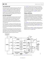
Controller Area Network (CAN) Implementation Guide
by Dr. Conal Watterson
Rev. A | Page 1 of 14
INTRODUCTION
The controller area network (CAN) is a standard for distributed
communications with built-in fault handling, specified for the
physical and data link layers of the open systems interconnection
(OSI) model in ISO-11898
1, 2
. CAN has been widely adopted in
industrial and instrumentation applications and the automotive
industry due to the inherent strengths of the communication
mechanisms used by CAN.
Features of CAN include
• Allowance for multiple masters on a bus
• Inherent priority levels for messages
• Bus arbitration by message priority
• Error detection and recovery at multiple levels
• Synchronization of data timing across nodes with separate
clock sources
At the physical layer, differential data transmission is supported
by the CAN protocol, providing advantages such as
• Bidirectional communications across a single pair of
twisted cables
• Increased immunity to noise
• Wide common-mode range allowing differences in ground
potential between nodes
IMPLEMENTING A CONTROLLER AREA NETWORK
This application note considers the following aspects of how CAN
is implemented in industrial applications:
• CAN implementation layers: how the CAN specification and
protocols relate to hardware/software and CAN transceiver
products
• CAN messages: how the message structure is fundamental
to error checking/recovery and arbitration
• Arbitration: how the carrier sense multiple access method
specified by CAN allows multiple driving nodes
• Error mechanisms: how the CAN specification inherently
enhances communication robustness
• Physical bus: what measures ensure proper communication
at the physical layer
• Isolation: signal and power isolation of CAN and integrated
isolation solutions for CAN
• Stress protection: mechanisms used in CAN for protecting
transceivers from electrical overstress
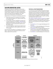
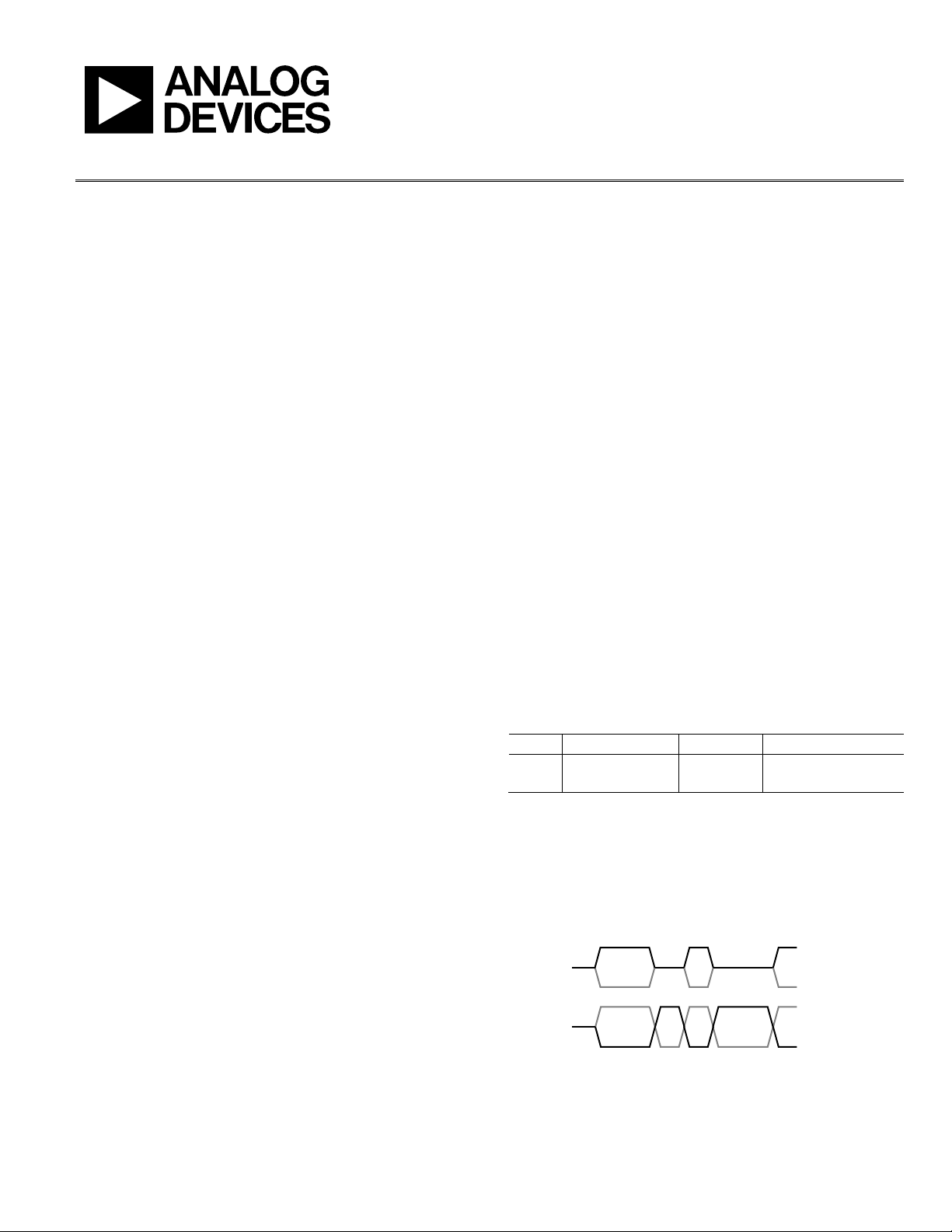
HOW CAN USES DIFFERENTIAL DATA
TRANSMISSION
In traditional differential data transmission (for example, RS-485
3
),
Logic 1 is transmitted as a voltage level high on one noninverting
transmission line and low on the inverting line. Correspondingly,
Logic 0 is transmitted as low on the noninverting line and high
on the inverting line. The receiver uses the difference in voltage
between the two lines to determine the Logic 1 or Logic 0 that
was transmitted, as shown in Table 1.
A driver on the bus can also be in a third state, with the driver
outputs in a high impedance state. If all nodes are in this condition,
the bus is in an idle state. In this condition, both bus lines are
usually at a similar voltage with a small differential.
Signaling for CAN differs in that there are only two bus voltage
states; recessive (driver outputs are high impedance) and dominant
(one bus line, CANH, is high and the other, CANL, is low), with
thresholds as shown in Table 1. Transmitting nodes transmit the
dominant state for Logic 0 and the recessive state for Logic 1.
An idle CAN bus is distinguished from recessive bit transmission
simply by detection of multiple recessive bits after an end of
frame or error frame.
Table 1. Comparison of CAN and RS-485 Voltage Levels
Logic RS-485 Levels CAN State CAN Levels
1 A − B ≥ +200 mV Recessive CANH − CANL ≤ 0.5 V
0 A − B ≤ −200 mV Dominant CANH − CANL ≥ 0.9 V
The two states of dominant and recessive are represented by the
CANH and CANL voltage levels shown in Figure 1 that compares
CAN signaling to RS-485. This signaling method is fundamental
both to the node arbitration and inherent prioritization of messages
with lower message IDs (more initial Logic 0s as the message is
serially transmitted).
0IDLE
CAN
CANH
CANL
INVERTING
NONINVERTING
RS-485/
RS-422
0 1 11 0 0
0
(D)
IDLE
1
(R)
0
(D)
1
(R)
1
(R)
1
(R)
0
(D)
0
(D)
NOTES
1. CAN BUS IDLE AFTER MULTIPLE RECESSIVE BITS.
10035-001
F
igure 1. Comparison of Differential Signaling for CAN and RS-485/RS-422
器件 Datasheet 文档搜索
AiEMA 数据库涵盖高达 72,405,303 个元件的数据手册,每天更新 5,000 多个 PDF 文件
