Datasheet 搜索 > 微控制器 > Microchip(微芯) > ATMEGA128-16MU 数据手册 > ATMEGA128-16MU 用户编程技术手册 1/386 页

¥ 143.535
ATMEGA128-16MU 用户编程技术手册 - Microchip(微芯)
制造商:
Microchip(微芯)
分类:
微控制器
封装:
VFQFN-64
描述:
8 位 megaAVR 微控制器,32KB 到 256KB 闪存我们在 RS Components 提供多款来自 Atmel 的 megaAVR 8 位微控制器。 每个微控制器均基于增强型 RISC 体系结构,并具有 QTouch 库支持。 所有微控制器类型具有不同 Kb 的系统内可编程内存、EEPROM 和 SRAM 以及不同引脚和封装类型。 **megaAVR 8 位微控制器类型** ATmega32 ATmega64 ATmega128 ATmega324 ATmega325 ATmega406 ATmega640 ATmega644 ATmega645 ATmega1280 ATmega1281 ATmega1284 ATmega2560 ATmega2561 ATmega3250 ATmega6450
Pictures:
3D模型
符号图
焊盘图
引脚图
产品图
页面导航:
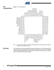
引脚图在P2P5P68P93P112P146Hot
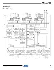
原理图在P3P10P66P93P94P96P97P113P118P119P121P123
封装尺寸在P369P370
型号编码规则在P368P374P375P376P378
封装信息在P369P376
应用领域在P34P50P61P64P273P276P284P286P287
电气规格在P90P375
导航目录
ATMEGA128-16MU数据手册
Page:
of 386 Go
若手册格式错乱,请下载阅览PDF原文件

Features
• High-performance, Low-power AVR
®
8-bit Microcontroller
• Advanced RISC Architecture
– 133 Powerful Instructions – Most Single Clock Cycle Execution
– 32 x 8 General Purpose Working Registers + Peripheral Control Registers
– Fully Static Operation
– Up to 16 MIPS Throughput at 16 MHz
– On-chip 2-cycle Multiplier
• High Endurance Non-volatile Memory segments
– 128K Bytes of In-System Self-programmable Flash program memory
– 4K Bytes EEPROM
– 4K Bytes Internal SRAM
– Write/Erase cycles: 10,000 Flash/100,000 EEPROM
– Data retention: 20 years at 85°C/100 years at 25°C
(1)
– Optional Boot Code Section with Independent Lock Bits
In-System Programming by On-chip Boot Program
True Read-While-Write Operation
– Up to 64K Bytes Optional External Memory Space
– Programming Lock for Software Security
– SPI Interface for In-System Programming
• JTAG (IEEE std. 1149.1 Compliant) Interface
– Boundary-scan Capabilities According to the JTAG Standard
– Extensive On-chip Debug Support
– Programming of Flash, EEPROM, Fuses and Lock Bits through the JTAG Interface
• Peripheral Features
– Two 8-bit Timer/Counters with Separate Prescalers and Compare Modes
– Two Expanded 16-bit Timer/Counters with Separate Prescaler, Compare Mode and
Capture Mode
– Real Time Counter with Separate Oscillator
– Two 8-bit PWM Channels
– 6 PWM Channels with Programmable Resolution from 2 to 16 Bits
– Output Compare Modulator
– 8-channel, 10-bit ADC
8 Single-ended Channels
7 Differential Channels
2 Differential Channels with Programmable Gain at 1x, 10x, or 200x
– Byte-oriented Two-wire Serial Interface
– Dual Programmable Serial USARTs
– Master/Slave SPI Serial Interface
– Programmable Watchdog Timer with On-chip Oscillator
– On-chip Analog Comparator
• Special Microcontroller Features
– Power-on Reset and Programmable Brown-out Detection
– Internal Calibrated RC Oscillator
– External and Internal Interrupt Sources
– Six Sleep Modes: Idle, ADC Noise Reduction, Power-save, Power-down, Standby, and
Extended Standby
– Software Selectable Clock Frequency
– ATmega103 Compatibility Mode Selected by a Fuse
– Global Pull-up Disable
• I/O and Packages
– 53 Programmable I/O Lines
– 64-lead TQFP and 64-pad QFN/MLF
• Operating Voltages
– 2.7 - 5.5V ATmega128L
– 4.5 - 5.5V ATmega128
• Speed Grades
– 0 - 8 MHz ATmega128L
– 0 - 16 MHz ATmega128
8-bit
Microcontroller
with 128K Bytes
In-System
Programmable
Flash
ATmega128
ATmega128L
Note: Not recommended for new
designs.
Rev. 2467S–AVR–07/09
器件 Datasheet 文档搜索
AiEMA 数据库涵盖高达 72,405,303 个元件的数据手册,每天更新 5,000 多个 PDF 文件
